


22 en | Installing the Power Supply Box AutoDome Power Supply Boxes
F.01U.250.895 | 1.0 | 2011.08 Installation Guide Bosch Security Systems, Inc.
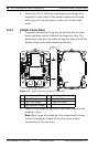
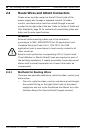
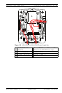
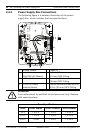
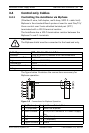
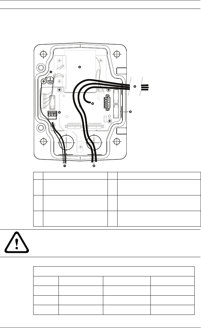
2.4.3 Power Supply Box Connections
The following figure is a detailed illustration of the power
supply box, which includes the fuse specifications.
1 Ground Screw 5 Power In
2 Transformer
(115/230 VAC Modes)
6 In/Out; 1/2 in.
(15 mm) NPS Fitting
3 In/Out to Dome 7 Power In; 3/4 in.
(20 mm) NPS Fitting
4 24 VAC to Dome
Interface Board
8 Control Data and Video In/Out;
3/4 in. (20 mm) NPS Fitting
C
O
N
T
R
O
L
T
O DOM
E
M
M
C
O
N
T
RO
L
IN
/
OU
T
G
ND
T
XD
R
XD
C
+
C
-
P101
1 2 3
6 5 4 3 2 1
3
P106
P105
P107
XF102 XF103
XF101
5 4 3 2 1
J103
J103
J
J103
J
1
0
2
1
1
1
1
1
J1
0
1
1
1
1
1
1
1
1
1
1
1
1
1
1
1
1
1
1
1
1
1
1
1
1
1
1
1
1
1
1
1
1
(LED)
6
5
4
3
2 1
G
ND
T
XD
R
XD
C
+
C
-
HTR DOME
(FUSE)
(FUSE)
)
)
(FUSE)
)
)
24V NC 24V
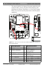
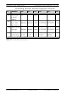
WARNING!
Fuse replacement by qualified service personnel only. Replace
with same type fuse.
Fuse Specifications
Volts XF101 Mains XF102 Camera XF103 Heater
24 V T 5.0 A T 2.0 A T 3.15 A
115 V T 1.6 A T 2.0 A T 3.15 A
230 V T 0.8A T 2.0 A T 3.15 A