


80 Converged Enhanced Ethernet Administrator’s Guide
53-1002163-02
Link aggregation overview
8
DRAFT: BROCADE CONFIDENTIAL
On each port, link aggregation control:
• Maintains configuration information to control port aggregation.
• Exchanges configuration information with other devices to form LAGs.
• Attaches ports to and detaches ports from the aggregator when they join or leave a LAG.
• Enables or disables an aggregator’s frame collection and distribution functions.
Each link in the Brocade FCoE hardware can be associated with a LAG; a link cannot be associated
with more than one LAG. The process of adding and removing links to and from a LAG is controlled
either statically, dynamically, or through LACP.
Each LAG consists of the following components:
• A MAC address that is different from the MAC addresses of the LAG’s individual member links.
• An interface index for each link to identify the link to neighboring devices.
• An administrative key for each link. Only links having the same administrative key value can be
aggregated into a LAG. On each link configured to use LACP, LACP automatically configures an
administrative key value equal to the port-channel identification number.
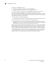
Figure 5 and Figure 6 show typical IP SAN configurations using LAGs. In a data center the Brocade
8000 switch fits into the top-of-the-rack use case where all the servers in a rack are connected to
the Brocade 8000 switch through Twinax copper or optical fiber cable. The database server layer
connects to the top-of-the-rack Brocade 8000 switch which is located in the network access layer.
The Brocade 8000 switch connects to Layer 2/Layer 3 aggregation routers which provide access
into the existing LAN. This connectivity is formed in a standard V-design or square-design. Both
designs use the LAG as the uplink to provide redundancy and improved bandwidth.