


32 Converged Enhanced Ethernet Administrator’s Guide
53-1002163-02
End to End FCoE using FC ISLs
5
DRAFT: BROCADE CONFIDENTIAL
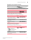
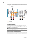
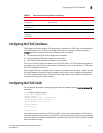
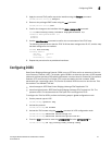
The following diagram shows a deployment scenario where FCoE initiators are connected to FCoE
and FC targets across multiple hops of FC ISLs.
FIGURE 3 Deploying FCoE across multiple hops of FC ISLs
FCoE Logical Port Numbering
A total of 24 FCoE logical ports on FCOE10-24 belong to 6 FCoE port groups. The port number
range is 0 through 23 and these belong to 6 FCoE port groups ranging from 0 through 3, 4 through
7, 8 through 11, 12 through 15, 16 through 19, and 20 through 23. For example, the FCoE ports on
a 24 port blade in the 4th slot is 4/0 through 4/23.
NOTE
This grouping is relevant only for bridging bandwidth considerations. A group of four ports that is
arranged in a bank has 10Gb of bridging bandwidth.
FCoE port-to-front end TenGigabit port mapping
Each of the FCoE logical ports in VF port mode is mapped to a corresponding front end TenGigabit
port such that the FCoE FLOGI received through the TenGigabit port is mapped and handled at the
corresponding FCoE logical port.
Fibre Channel
FCoE
Storage
FCoE,
Storage
FC
Storage
Arrays
DCX FC Core
DCX FC Edge
DCX/DCX-4s
FCoE Edge
Aggregation
Switch/Router
SAN
Tape
Libraries
Data Center Bridging
Ethernet