


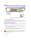

Connecting to the Network
3-8 Installation
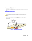
2. Observe the LANVIEW LEDs. After a successful boot, the PWR LED turns ON (green). If the
PWR LED is amber, there is no power redundancy. Check the power cord connections and the
power source. If there are no problems with the power cord connections or power source and
the PWR LED is still amber, contact Cabletron Systems for support. Refer to Section 1.2 for
details.
3.4 CONNECTING TO THE NETWORK
This section provides the procedures for connecting unshielded twisted pair (UTP) segments from
the network or other devices to the 2H253-25R. To make connections to an optional HSIM or
VHSIM installed in the HSIM/VHSIM slot of the 2H253-25R, refer to the associated user’s guide
for the HSIM or VHSIM.
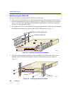
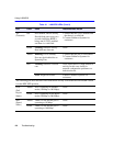
Each of the two RJ21 connectors on the front panel have 12 UTP port connections. These ports (1
through 24) are 10/100 ports with internal crossovers. When connecting a workstation, use a
straight-through cable. When connecting networking devices, such as another bridge, repeater, or
router, use a crossover cable.
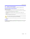
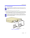
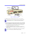
To connect an RJ21, proceed as follows:
1. Ensure that the device connected to the other end of the segment is powered on.
2. If using an RJ21 straight connector, plug it into the appropriate RJ21 port as shown in
Figure 3-6.
NOTE
If the 2H253-25R is being installed in a network using SmartTrunking, there are rules
concerning the network cable and port configurations that must be followed for
SmartTrunking to operate properly. Before connecting the cables, refer to the Cabletron
Systems
SmartTrunk User’s Guide
for the configuration information.
NOTE
If a port is connected to a 10-Mbps segment, Category 3 Unshielded Twisted Pair (UTP)
cable is sufficient to use. However, if the segment is to carry 10- or 100-Mbps
transmissions, use only Category 5 UTP cabling that has an impedance of between 85
and 111 ohms.