


SIMM Upgrade
Optional Installations and Mode Switch Bank Settings B-7
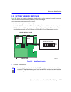
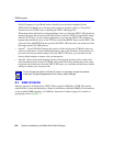
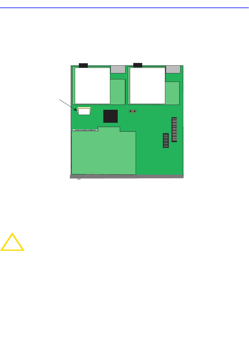
B.4.1 Locating SIMMs
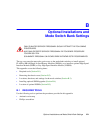
Figure B-3 shows the two locations of the DRAM SIMM connector.
Figure B-3 SIMM Slot Locations
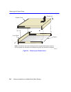
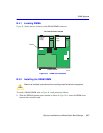
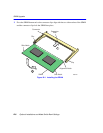
B.4.2 Installing the DRAM SIMM
To install a DRAM SIMM, refer to Figure B-4 and proceed as follows:
1. With the SIMM alignment notch oriented as shown in Figure B-4, insert the SIMM down
between the connector teeth.
!
CAUTION
Observe all antistatic precautions when handling sensitive electronic equipment.
2504-84
DRAM
FRONT PANEL
TOP VIEW WITHOUT COVER
Primary
Power
Supply
Redundant
Power
Supply