


Using LANVIEW
4-2 Troubleshooting
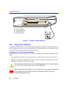
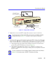
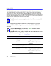
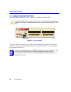
The LED MODE switch is located on the front panel of the 2H253-25R as shown in Figure 4-1.
This switch enables the user to change the function of the port LEDs. When the LED MODE
switch is moved to the left, the LEDs indicate the receive (RX) and transmit (TX) status of the
respective fixed ports (ports 1 through 24). When the LED MODE switch is moved to the right, the
port LEDs indicate whether the respective ports are operating in the standard or full duplex mode
(FDX) and if their operating speed (SPD) is 10 or 100 Mbps.
Table 4-1 describes the LED indications and provides recommended actions as appropriate.
Refer to the HSIM or VHSIM user’s guide for a description of the HSIM or VHSIM LED
indications.
NOTE
NOTE
NOTE
NOTE
The LED mode switch does not change the function of any LEDs on an installed HSIM
or VHSIM.
NOTE
NOTE
NOTE
NOTE
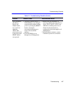
The terms flashing, blinking, and solid used in Table 4-1 indicate the following:
Flashing indicates an LED is flashing randomly.
Blinking indicates an LED is flashing at a steady rate (approximately 50% on, 50% off).
Solid indicates a steady LED light. No pulsing.
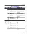
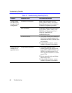
Table 4-1 LANVIEW LEDs
LED Color State Recommended Action
PWR Off Device electronics not
receiving power from power
supply(ies).
1.Ensure that the power cords are
plugged in correctly and that there is
power at the power source.
2.Contact Cabletron Systems for
assistance.
Green Functional. Power supply(ies)
operating normally.
None.
Amber Indicates loss of power supply
redundancy.
1.Ensure that the power cords are
plugged in correctly and that there is
power at the power source.
2.Contact Cabletron Systems for
assistance.