


CHAPTER 4: CONNECTING TO THE NETWORK
4-4 SEH USER’S GUIDE
c. Check the cable for continuity.
d. Check that the twisted pair connection meets dB loss and cable
specifications outlined in Chapter 2.
e. Check that the crossover switch is in the correct position.
If a link is not established, contact Cabletron Systems Technical Support.
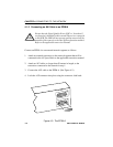
4.1.3 Connecting a Fiber Segment to an EPIM-F1/F2/F3
When connecting a fiber optic link segment to an EPIM-F1, EPIM-F2, or
EPIM-F3 keep the following in mind:
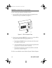
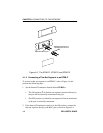
• When connecting a fiber optic link segment with SMA 906
connectors to an EPIM-F1 with SMA ports, ensure that half
alignment sleeves are in place on each connector. A full alignment
sleeve will damage the receive port. SMA 905 connectors do not
need alignment sleeves.
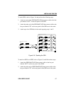
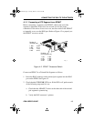
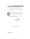
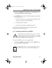
• To connect a segment with ST connectors to an EPIM-F2 /F3,
keep in mind that ST connectors attach to ST ports much like BNC
connectors attach to BNC ports. Insert the connector into the port
with the alignment key on the connector inserted into the
alignment slot on the port. Turn the connector to lock it down.
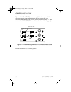
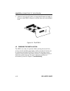
• The physical communication link consists of two strands of fiber
optic cabling: the Transmit (TX) and the Receive (RX). The
Transmit strand from the applicable port on the module is
connected to the Receive port of a fiber optic Ethernet device at the
other end of the segment. The Receive strand of the applicable port
on the module is connected to the Transmit port of the fiber optic
Ethernet device.
• Label the fiber optic cable to indicate which fiber is Receive and
which is Transmit. Fiber optic cable purchased from Cabletron
Systems is labeled so that one fiber is labeled 1 and the other fiber
is labeled 2 at both ends of the cable. For cable not purchased from
Cabletron Systems, label the cable as described above.
SEH Book Page 4 Tuesday, March 19, 1996 4:12 PM