


EPIM CABLE SPECIFICATIONS
SEH USER’S GUIDE A-7
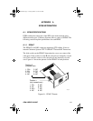
A.2 EPIM CABLE SPECIFICATIONS
The following subsections provide cable specifications for the various
EPIMs use in the SEH.
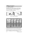
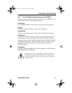
A.2.1 Multimode Fiber Optic Cable Specifications
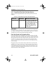
Table A-1 shows Multimode Fiber Optic Cable specifications for the
EPIM-F1 and EPIM-F2 modules.
Attenuation
Test the fiber optic cable with a fiber optic attenuation test set adjusted for
an 850 nm wavelength. This test verifies that the signal loss in a cable is
within an acceptable level. Table A-1 shows the attenuation for each
Multimode cable type.
Fiber Optic Budget and Propagation Delay
When determining the maximum fiber optic cable length, take into
consideration the fiber optic budget delay and total network propagation
before fiber optic cable runs are incorporated in any network design.
Fiber optic budget is the combination of the optical loss due to the fiber
optic cable, in-line splices, and fiber optic connectors.
Propagation delay is the amount of time it takes data to travel from the
sending device to the receiving device. Total propagation delay allowed
for the entire network must not exceed 25.6 µs in one direction (51.2 µs
round trip). If the total propagation delay between any two nodes on the
network exceeds 25.6 µs, use bridges.
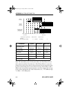
Table A-1. Multimode Fiber Optic Cable Specifications
Cable Type Attenuation Maximum Cable Length
50/125 µm 13.0 dB or less The maximum allowable fiber
optic cable length is 2 km
(2187.2 yds). However, IEEE
802.3 specifications allow for a
maximum of 1 km (1093.6 yds).
62.5/125 µm 16.0 dB or less
100/140 µm 19.0 dB or less
SEH Book Page 7 Tuesday, March 19, 1996 4:12 PM