


INSTALLATION
Page 3-9
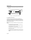
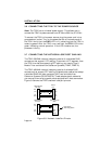
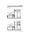
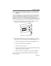
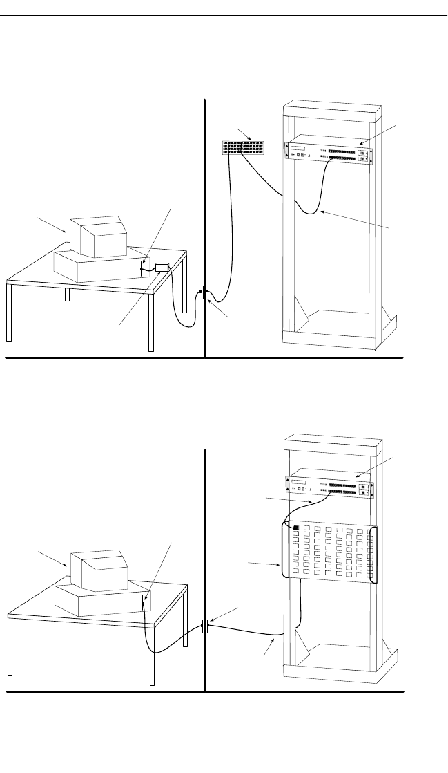
Figure 3-9 illustrates possible configurations for both the TRXI-24A
and TRXI-44A.
Figure 3-9. Configuration Examples for TRXI-24A and TRXI-44A
Punchdown
Block
WIRING CLOSET
OFFICE
Token Ring
Station
Token Ring
Network Interface Card
Wall
Jack
UTP
Lobe Cable
WALL
TRXI-24A
TRXI-24
TOKEN RING HUB
WITH
LANVIEW®
RI
RO
TRMF
STP to UTP
Type 3 Media Filter
TRXI-24
TOKEN RING HUB
WITH
LANVIEW®
RI
RO
Patch
Panel
MIC Data
Connector
WIRING CLOSET
OFFICE
Token Ring
Station
Token Ring
Network Interface Card
Wall
Jack
STP
Lobe Cable
WALL
TRXI-44A