3–7
OPERATIONS AND TIMING
COPYRIGHT
©
1998 CANON INC. CANON NP6621 REV.0 FEB. 1998 PRINTED IN JAPAN (IMPRIME AU JAPON)
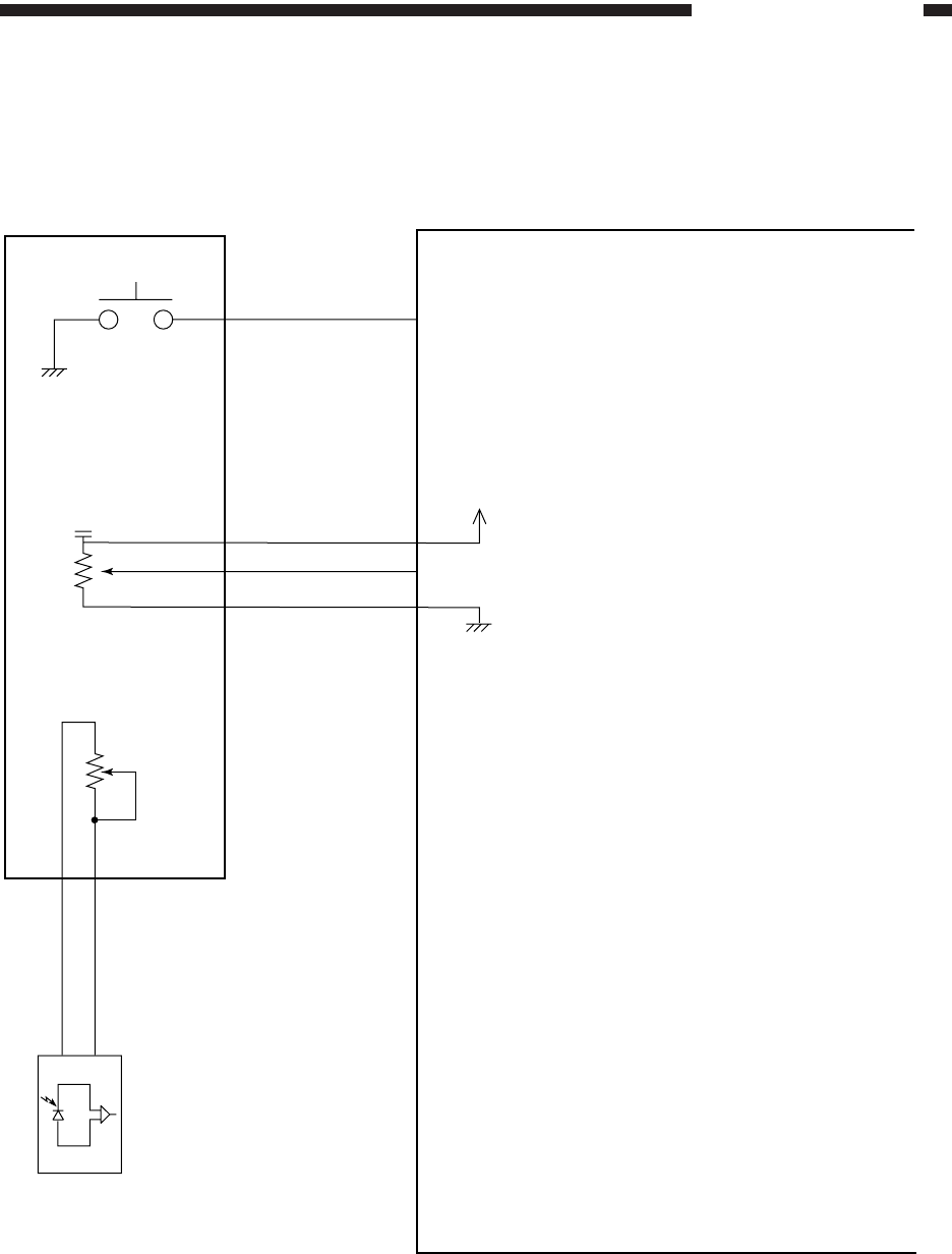
5. Inputs to the DC Controller PCB (5/5)
Figure 3-107
DC controller PCB
AEVR1
AEVR2
CDC
J306-7
-8
-9
Adjusts the developing DC bias
SRSW
VR850
SW850
Service switch PCB
Service switch
Density correction volume
AE sensor
adjustment volume
VR851
AE sensor (2/2)
When the switch turns on, '0'.
(starts service mode)
+5V


