5–16
INSTALLATION
COPYRIGHT
©
1998 CANON INC. CANON NP6621 REV.0 FEB. 1998 PRINTED IN JAPAN (IMPRIME AU JAPON)
VI. CASSETTE HEATER KIT 5 INSTALLATION
PROCEDURE
A. Unpacking
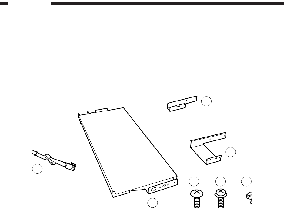
Open the shipping box, and check to make sure that none of the parts shown in Fig. 5-601 is missing.
Figure 5-601
q Cassette Heater .................... 1
w Mounting plate 1 .................... 1
e Mounting plate 2 .................... 1
r Relay harness ....................... 1
t Cord clamp ............................ 1
y Binding screw (black; M4×6) . 2
u TP screw (white; M3×6) ........ 2
4
6 7 5
2
3
1


