


38-71
Cisco Catalyst Switch Module 3110 and 3012 for IBM BladeCenter Software Configuration Guide
OL-12189-01
Chapter 38 Configuring IP Unicast Routing
Configuring Multi-VRF CE
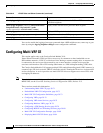
Understanding Multi-VRF CE
Multi-VRF CE is a feature that allows a service provider to support two or more VPNs overlapping IP
addresses among the VPNs. Multi-VRF CE uses input interfaces to distinguish routes for different VPNs
and forms virtual-packet-forwarding tables by associating one or more Layer 3 interfaces with each
VRF. Interfaces in a VRF can be either physical, such as Ethernet ports, or logical, such as VLAN switch
virtual interfaces (SVIs), but an interface cannot belong to more than one VRF at any time.
Note Multi-VRF CE interfaces must be Layer 3 interfaces.
Multi-VRF CE includes these devices:
• Customer-edge (CE) devices provide customers access to the service-provider network over a data
link to one or more provider edge routers. The CE device advertises the site local routes to the router
and learns the remote VPN routes from it. A switch can be a CE.
• Provider-edge (PE) routers exchange routing information with CE devices by using static routing or
a routing protocol such as BGP, RIPv2, OSPF, or EIGRP. The PE is only required to maintain VPN
routes for those VPNs to which it is directly attached. The PE only needs to maintain all of the
service-provider VPN routes. Each PE router maintains a VRF for each of its directly connected
sites. Multiple interfaces on a PE router can be associated with a single VRF if all of these sites
participate in the same VPN. Each VPN is mapped to a specified VRF. After learning local VPN
routes from CEs, a PE router exchanges VPN routing information with other PE routers by using
internal BGP (IBPG).
• Provider routers or core routers are any routers in the service provider network that are not attached
to CE devices.
With multi-VRF CE, multiple customers can share one CE, and only one physical link is used between
the CE and the PE. The shared CE maintains separate VRF tables for each customer and switches or
routes packets for each customer based on its own routing table. Multi-VRF CE extends limited PE
functionality to a CE device. It can then maintain separate VRF tables to extend the privacy and security
of a VPN to the branch office.
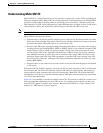
Figure 38-7 is an example of switches as multiple virtual CEs. This scenario is suited for customers who
have low bandwidth requirements for their VPN service, for example, small companies. In this case,
multi-VRF CE support is required in the switches. Because multi-VRF CE is a Layer 3 feature, each
interface in a VRF must be a Layer 3 interface.