


5-69
Cisco TelePresence System
OL-16441-01
Chapter 5 Upgrading a Cisco TelePresence System 3000 to a Cisco TelePresence System 3200
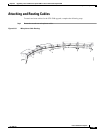
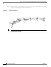
Attaching and Routing Cables
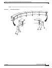
Tip Before plugging the Light fixture power cables into the unit, label each one. For example, 5’ Left light,
4’ Right light.
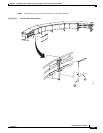
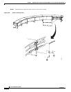
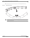
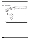
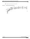
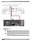
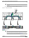
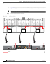
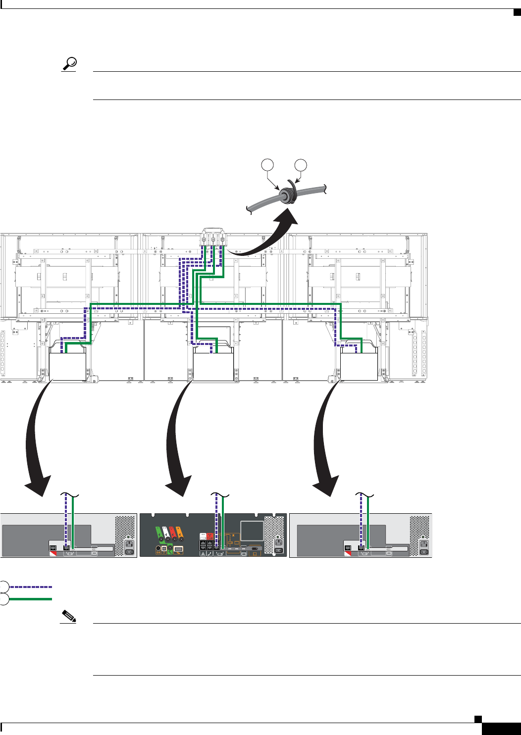
Step 7 Attach and route the power-over-Ethernet and HDMI cables for the camera.
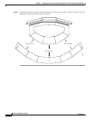
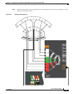
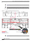
Figure 5-59 Cabling the Camera Assembly
Note The camera cluster can experience radio frequency interference issues if the camera Ethernet and
HD
video cables are routed, bundled, or tied together. Cisco recommends that you route the Ethernet and
HD
video cables separately and use cable ties to tie them to opposite sides of the frame. In addition,
attach the ferrite core and use tie wraps to secure them as shown in Figure 5-59.
RJ45 Power over Ethernet
HDMI connector
204165
1
0
5
14
15