


22-9
Catalyst 3750-X and 3560-X Switch Software Configuration Guide
OL-21521-01
Chapter 22 Configuring Optional Spanning-Tree Features
Understanding Optional Spanning-Tree Features
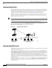
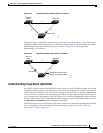
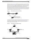
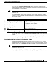
If link L1 fails as shown in Figure 22-7, Switch C cannot detect this failure because it is not connected
directly to link L1. However, because Switch B is directly connected to the root switch over L1, it detects
t
he failure, elects itself the root, and begins sending BPDUs to Switch C, identifying itself as the root.
When Sw
itch C receives the inferior BPDUs from Switch B, Switch C assumes that an indirect failure
h
as occurred. At that point, BackboneFast allows the blocked interface on Switch C to move
i
mmediately to the listening state without waiting for the maximum aging time for the interface to expire.
BackboneFast then transitions the Layer 2 interface on Switch C to the forwarding state, providing a path
fr
om Switch B to Switch A. The root-switch election
takes approximately 30 seconds, twice the Forward
Delay time if the default Forward Delay time of 15 seconds is set. Figure 22-7 shows how BackboneFast
reconfigures the topology
to account for the failure of link L1.
Figure 22-7 BackboneFast Example After Indirect Link Failure
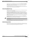
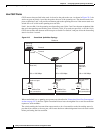
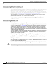
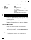
If a new switch is introduced into a shared-medium topology as shown in Figure 22-8, BackboneFast is
not activated because the inferior BPDUs d
id not come from the recognized designated switch
(Switch B). The new switch begins sending inferior BPDUs that indicate it is the root switch. However,
t
he other switches ignore these inferior BPDUs, and the new switch learns that Switch B is the
d
esignated switch to Switch A, the root switch.
Figure 22-8 Adding a Switch in a Shared-Medium Topology
L1
L2 L3
Switch C
Switch A
(Root)
Switch B
Link failure
44964
BackboneFast changes port
through listening and learning
states to forwarding state.
Switch A
(Root)
Switch C
Switch B
(Designated bridge)
Added switch
44965
Blocked port