


11
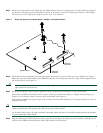
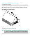
Closing a Chassis with a Plug-In CPU/Mainboard
Perform this procedure with electrical power to the router turned OFF and with network interface cables disconnected.
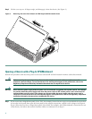
Step 1 Make sure that the ejector levers are fully open. Carefully insert the CPU/mainboard into the chassis slot until the
connector is engaged, and then close the ejector levers to fully seat the CPU/mainboard connector. (See Figure 12.)
Step 2 Tighten the two captive retention screws; there is one at each edge of the CPU/mainboard.
Step 3 If your router has a hinged front panel, engage the hinges and close the front panel; then tighten the two captive screws
behind the small access door at the right-hand edge. (See Figure 4 on page 5 for reference.)
If your router does not have a hinged front panel, skip to Step 4.
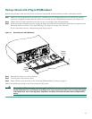
Figure 12 Reinstalling the CPU/Mainboard
Step 4 Reinstall the chassis on a rack or desktop.
Step 5 Connect power and interface cables.
Step 6 Power ON the router, and refer to the “Verifying AIM Installation” section on page 12.
Observe the following warning if your Cisco router uses DC power:
Warning
After wiring the DC power supply, remove the tape from the circuit breaker switch handle and reinstate power by
moving the handle of the circuit breaker to the ON position. To see translations of the various warnings that appear
in this publication, refer to the Regulatory Compliance and Safety Information document that accompanied this
device.
62489
Captive
retention
screw
Ejector levers
Captive
retention
screw