


3
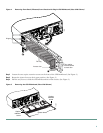
The following warning applies to all routers:
Warning
Before opening the chassis, disconnect the telephone-network cables to avoid contact with telephone-network
voltages. To see translations of the warnings that appear in this publication, refer to the Regulatory Compliance
and Safety Information document that accompanied this device.
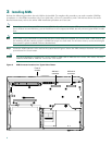
Opening a Chassis of 1-RU Height
Perform this procedure with electrical power to the router turned OFF, with network interface cables disconnected, and with
the router removed from its mounting rack.
Step 1 Remove the screws from the top of the chassis.
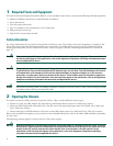
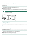
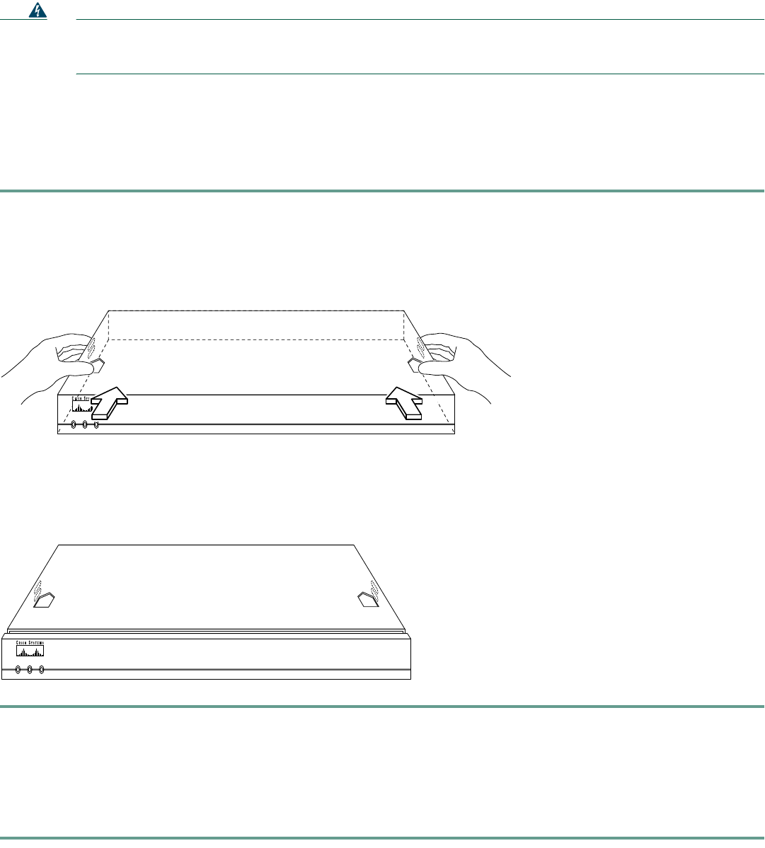
Step 2 Slide the top half of the chassis toward the rear. (See Figure 1.)
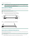
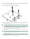
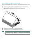
Step 3 Separate the top half of the chassis from the bottom half. (See Figure 2.)
Figure 1 Sliding Top Half of Chassis Toward the Rear—Chassis of 1-RU Height
Figure 2 Top Half of Chassis Ready for Removal—Chassis of 1-RU Height
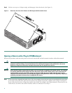
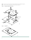
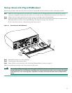
Opening a Chassis of 2-RU Height with Removable Cover
Perform this procedure with electrical power to the router turned OFF, with network interface cables disconnected, and with
the router removed from its mounting rack.
Step 1 Remove the screws from the top of the cover (typically five or six screws, depending on the router model). Set the screws
aside in a safe place.
Step 2 If your router has a blank cover plate in the upper right network-module slot, and displays the message LOOSEN
SCREW TO REMOVE COVER, loosen the captive screw at the left edge of the blank cover.
POWER RPS ACTIVITY
H11658
Cisco 2600
SERIES
H11659
POWER RPS ACTIVITY
Cisco 2600
SERIES