


5
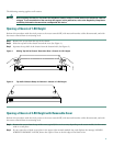
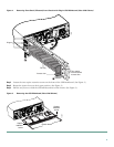
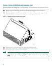
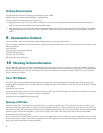
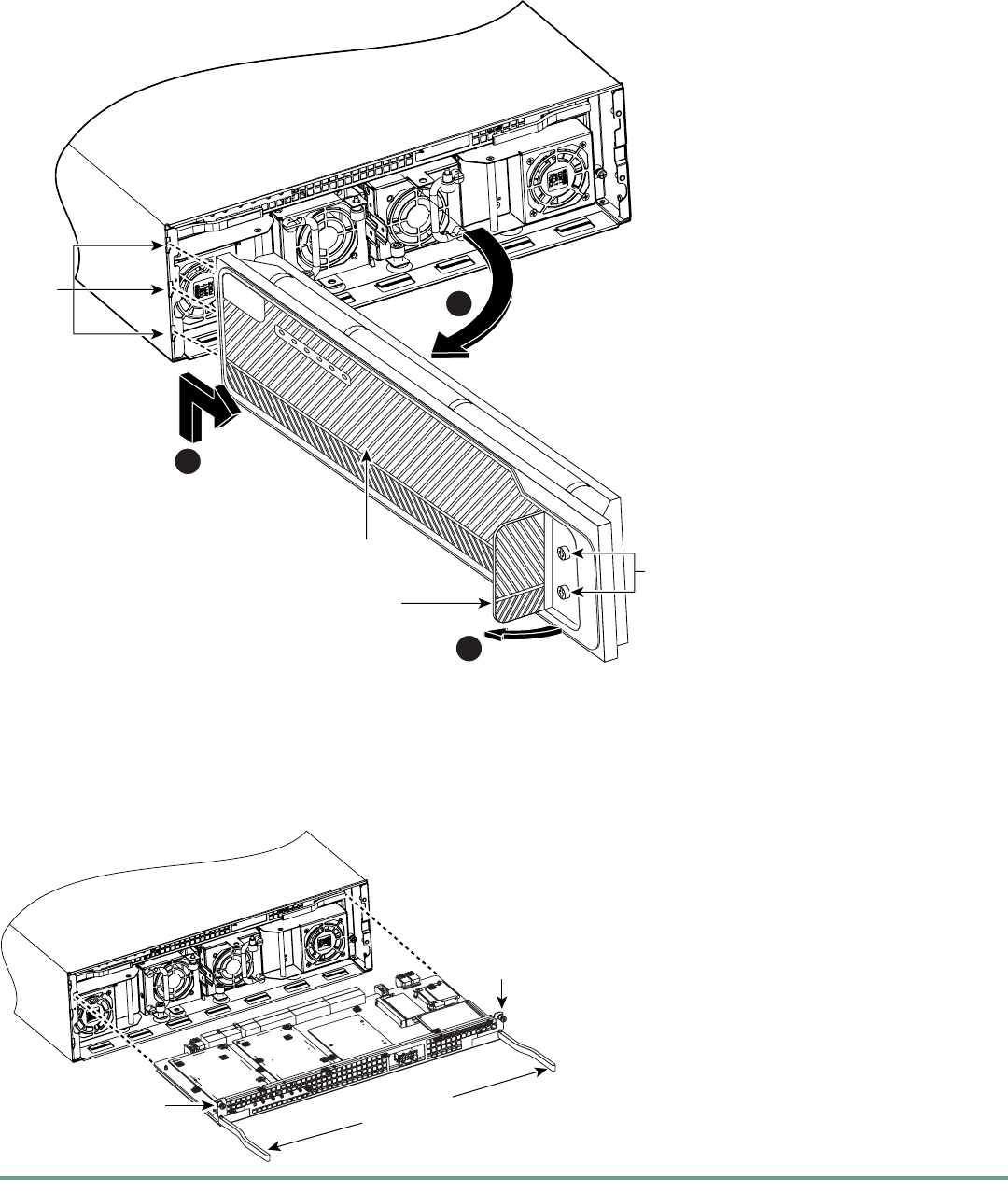
Figure 4 Removing Front Panel (If Present) from Chassis with Plug-In CPU/Mainboard (Cisco 3745 Shown)
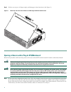
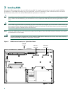
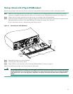
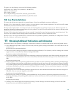
Step 2 Loosen the two captive retention screws on the front of the CPU/mainboard. (See Figure 5.)
Step 3 Rotate the ejector levers to their open position. (See Figure 5.)
Step 4 Pull the tray levers to slide the CPU/mainboard out of the chassis. (See Figure 5).
Figure 5 Removing the CPU/Mainboard (Cisco 3745 Shown)
72848
Hinges
Fan tray
Access door
Two captive
screws behind
access door
3
2
1
72849
Captive
retention
screw
Ejector levers
Captive
retention
screw