


7
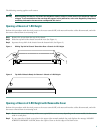
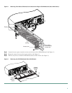
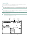
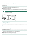
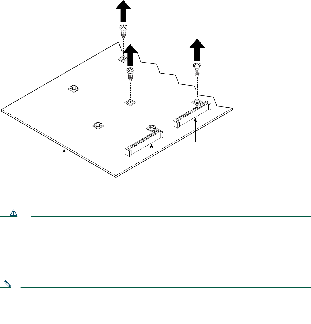
Step 2 Remove screws from the system board near the AIM connector that you are going to use—screws labeled A in Figure 7
are present in all chassis; screws labeled B are present in all chassis except Cisco 2600 series chassis of 1-RU height.
The screws in a Cisco 3660 router require use of a Torx-15 screwdriver.
Figure 7 Removing Screws from System Board—AIM Slot 1 Installation Shown
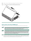
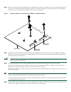
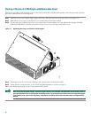
Step 3 Install the two metal standoffs (from the appropriate mounting kit) in place of the two screws labeled A in Figure 7.
Make sure that the screw threads on the standoffs match the screws that you removed in Step 2. Hand tighten with a
1/4-inch nut driver. (See Figure 8.).
Caution Make sure that the standoffs are installed straight. Tighten them gently but firmly. The shoulder must be seated
tight against the system board.
Step 4 Install the threaded or snap-in plastic standoff (from the appropriate mounting kit) in the system board.
If the plastic standoff is threaded, install it in place of the screw labeled B in Figure 7. Tighten it firmly using your
fingers, or very carefully using a 3/16-inch open-end wrench. (See Figure 8.)
If the plastic standoff is the snap-in type, press it firmly into the nonthreaded hole in the system board to be sure it is
locked to the board.
Note For a 1-RU chassis, the plastic standoff snaps into the system board. Be sure to insert the locking end of the standoff
into the system board. The locking end is the shortest end of the standoff.
For all other chassis types, the plastic standoff is threaded. Make sure that it is installed straight and that the shoulder
is seated against the system board.
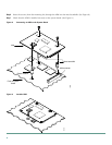
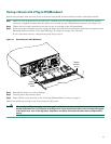
Step 5 Plug the AIM into the AIM connector on the system board. (See Figure 8.) Make sure that the plastic standoff fits into
the hole in the AIM board and that the AIM is fully seated in the connector.
72107
AIM slot 1
connector
AIM slot 0
connector
System board
A
A
A
A
B
B