


1-8
Catalyst 3750-X and 3560-X Switch Hardware Installation Guide
OL-19593-01
Chapter 1 Product Overview
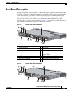
Front Panel Description
For information about SFP modules, see your SFP module documentation and the “Installing SFP and
SFP+ Modules” section on page 2-25. For cable specifications, see Appendix B, “Connector and Cable
Specifications.”
Note When ordering or using CX1 cables, ensure that the version identifier is 2 or higher.
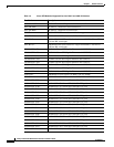
The Catalyst 3560-X switch supports the SFP module patch cable (CAB-SFP-50CM), a 0.5-meter,
copper, passive cable with SFP module connectors at each end. This cable is only used with 1-Gigabit
Ethernet SFP ports to connect two Catalyst 3560-X switches in a cascaded configuration.
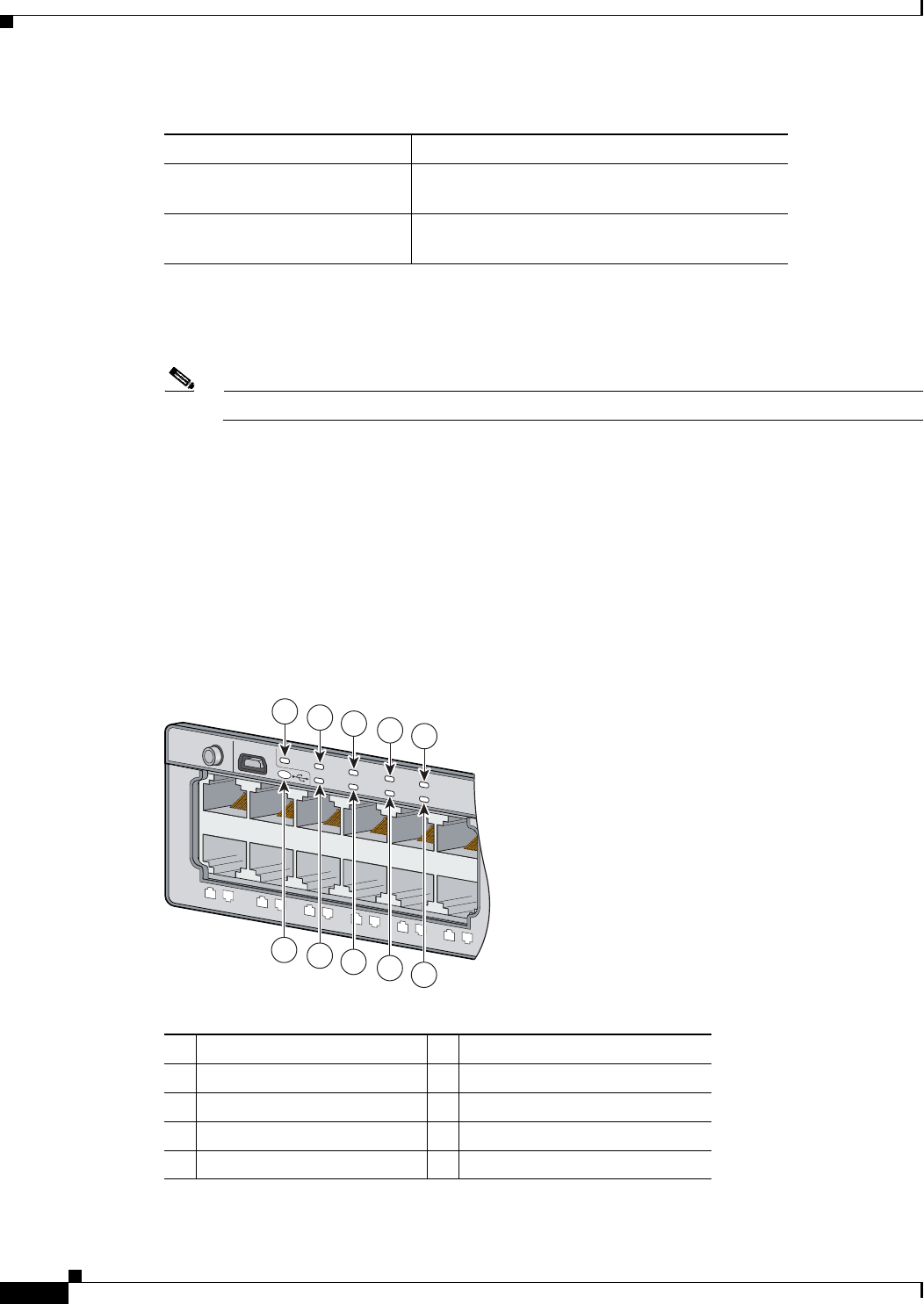
LEDs
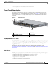
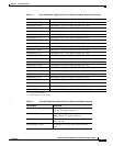
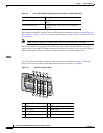
You can use the switch LEDs to monitor switch activity and its performance. Figure 1-2 shows the
Catalyst 3750-X switch LEDs and the Mode button that you use to select a port mode.
Figure 1-2 Switch Front Panel LEDs
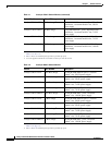
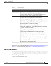
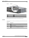
SFP-H10GB-CU3M= 10 GBASE-CU Twinax SFP+ cable assembly, 3
meters
SFP-H10GB-CU5M= 10 GBASE-CU Twinax SFP+ cable assembly,
5meters
Table 1-5 Cisco SFP+ Modules Supported for the 3750-X and 3560-X Switches
Part Number Description
1 System LED 6 USB console port LED
2 XPS
1
LED
1. XPS = Expandable power system.
7 S-PWR (StackPower) LED
2
3 Status LED 8 Master LED
2
4 Speed LED 9 Stack LED
2
5 Duplex LED 10 PoE+ LED
3
SYST
XPS
STAT
SPEED
DUPLX
PoE
STAC K
MAST
S-PWR
MODE
CONSOLE
1
2
3
4
5
6
7
8
9
10
11
12
EN
1
251962
7
5
4
3
2
8
9
10
6