


1-15
Catalyst 3750-X and 3560-X Switch Hardware Installation Guide
OL-19593-01
Chapter 1 Product Overview
Rear Panel Description
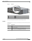
Rear Panel Description
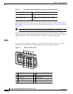
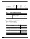
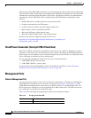
The switch rear panel has a ground connector, an RJ-45 console port, an RJ-45 10/100 management port,
a USB Type A connector, two StackWise connectors (only Catalyst
3750-X switches), two fan modules,
an XPS-2200 connector, a StackPower connector (only Catalyst
3750-X switches), and two power
supply module slots. See
Figure 1-6, and the descriptions on the following pages. Figure 1-6 shows the
Catalyst 3750-X-48 PoE+ switch, which has one connector for either a StackPower or an XPS
connection, and one connector only for StackPower.
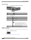
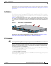
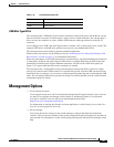
Figure 1-7 shows the Catalyst 3560-X switch rear
panel, which has one connector for XPS and no StackPower connector.
Figure 1-6 Catalyst 3750-X Switch Rear Panel
Figure 1-7 Catalyst 3560-X Switch Rear Panel
1 Ground connector 8 Fan modules
2 RJ 45 console port LED 9 StackPower or XPS-2200 connector
3 RJ-45 console port 10 StackPower connector
4 RJ-45 10/100 management port 11 Power supply modules (AC power supply
modules shown)
5 USB Type A connector 12 AC power (input) status LED
6 Stack cable connectors 13 Power supply (output) status LED
7 Reset button
RES
ET
CON
S
OLE
STACK 1
STACK 2
AUX
A
C
OK
C3KX
-P
WR-715W
AC
PS
O
K
A
C
OK
C3KX
-P
WR-715W
AC
PS
OK
S-PWR
XPS
S
-
PW
R
1
3
4
5
6
7
8
9
10
11
12
13
12
251961
13
2
RES
ET
S
E
R
IA
L
XPS
A
C
OK
C3K
X
-P
WR-715W
AC
PS
OK
CON
SOLE
10
/100T
X
1
3
4
5
6
7
8
11
253392
12
2
9
10