


3-4
Catalyst 3750-X and 3560-X Switch Hardware Installation Guide
OL-19593-01
Chapter 3 Power Supply and Fan Module Installation
Power Supply Module Overview
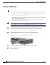
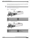
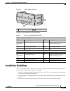
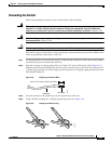
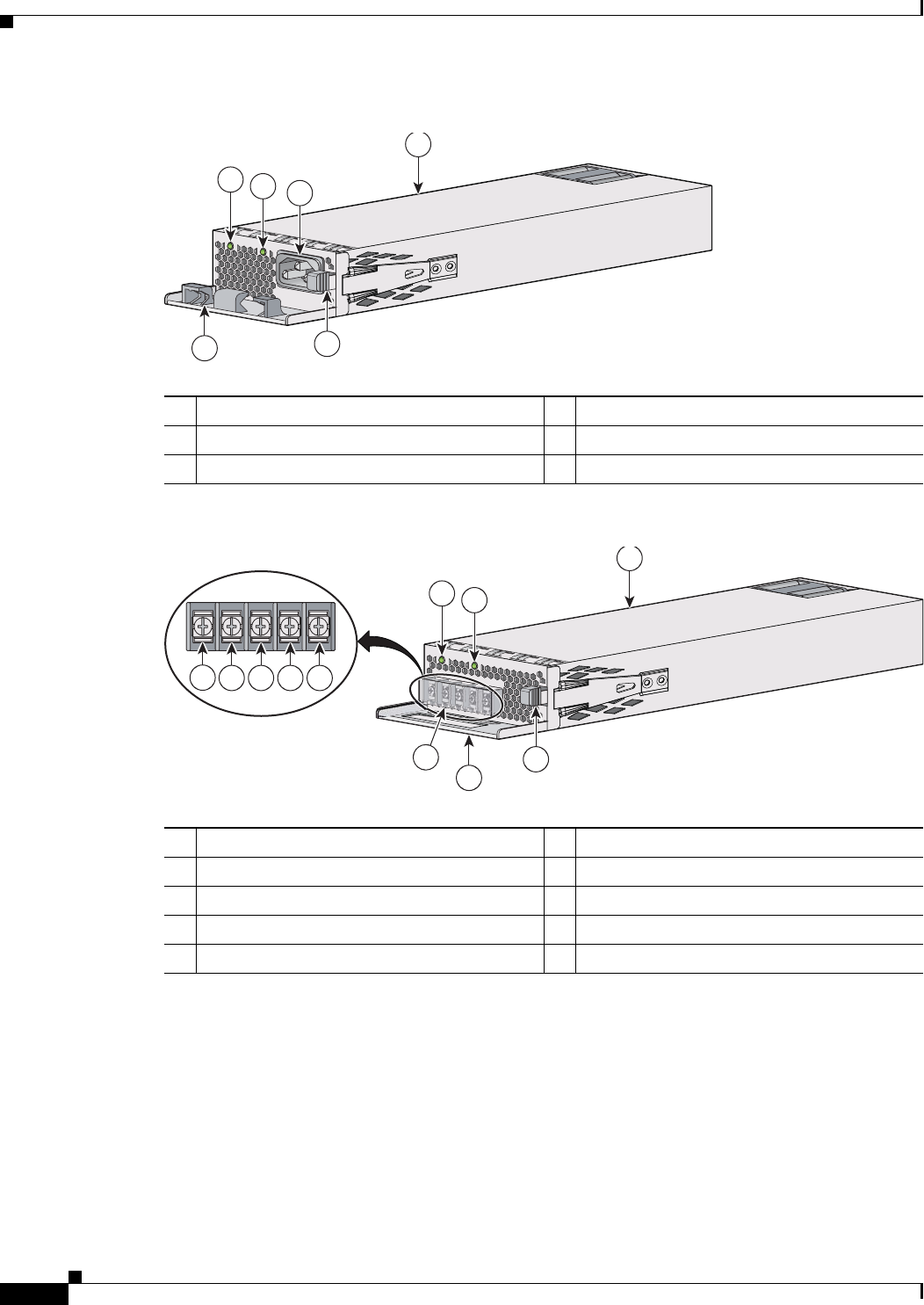
Figure 3-3 350-W AC Power Supply Module
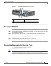
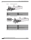
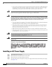
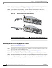
Figure 3-4 440-W DC Power Supply Module
If no power supply is installed in a power supply slot, install a power supply slot cover (Figure 3-5).
1 350-W AC power supply module 4 AC power cord connector
2 AC OK LED 5 Release latch
3 PS OK LED 6 Power cord retainer
AC OK
C3KX-PWR-350WAC
P
S
OK
207488
1
6
2
3
4
5
1 440-W DC power supply module 6 Grounding terminal
2 DC OK LED 7 Release latch
3 PS OK LED 8 Extraction handle
4 Input power terminals (positive polarity) 9 Terminal block safety cover
5 Input power terminals (negative polarity)
DC
OK
C3KX-PWR-440WDC
PS OK
253562
1
8
2
3
7
4
5 6 5 4
I
N
P
U
T
-
3
6
TO -
7
2
V
/
1
2
A
OUT
P
U
T
44W
M
AX
/2
2
A
9