


3-15
Catalyst 3750-X and 3560-X Switch Hardware Installation Guide
OL-19593-01
Chapter 3 Power Supply and Fan Module Installation
Installing a Fan Module
Installing a Fan Module
Note There must be a fan module in both fan module slots.
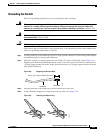
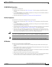
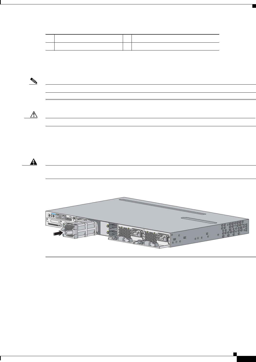
Step 1 Pinch the fan release handle, and slide the fan out.
Caution You should replace a failed fan module within 5 minutes to avoid overheating the switch.
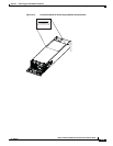
Step 2 Insert the new fan module into the fan slot, and firmly push the module) into the slot, applying pressure
to the end of the module, not the extraction handles (
Figure 3-18). When correctly inserted, the fan
module is flush with the switch rear panel. When the fan is operating, a green LED is on in the top left
corner of the fan.
Warning
Do not reach into a vacant slot or chassis while you install or remove a module or a fan. Exposed
circuitry could constitute an energy hazard.
Statement 206
Figure 3-18 Inserting the Fan Module in the Switch
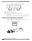
Finding the Fan Module Serial Number
If you contact Cisco Technical Assistance regarding a fan module, you need to know the fan module
serial number. See
Figure 3-19 for the serial number location.
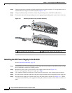
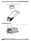
1 Fan LED 3 Retainer clip
2 Exhaust vent 4 Extraction handles
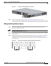
R
E
S
ET
C
ONSOLE
STACK 1
STACK 2
A
U
X
A
C
OK
C3K
X
-P
WR
-715W
AC
PS
OK
A
C
OK
C3K
X
-P
WR-715W
AC
PS
OK
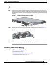
S-PWR
XPS
S
-
PW
R
253162