


3-9
Catalyst 3750-X and 3560-X Switch Hardware Installation Guide
OL-19593-01
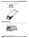
Chapter 3 Power Supply and Fan Module Installation
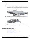
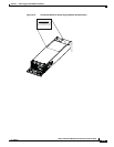
Installing a DC Power Supply
Grounding the Switch
Follow the grounding procedures at your site and observe these warnings:
Warning
This equipment must be grounded. Never defeat the ground conductor or operate the equipment in the
absence of a suitably installed ground conductor. Contact the appropriate electrical inspection
authority or an electrician if you are uncertain that suitable grounding is available.
Statement 1024
Warning
When installing or replacing the unit, the ground connection must always be made first and
disconnected last.
Statement 1046
Caution Follow the grounding procedure instructions, and use a UL-listed lug (included in the accessory kit).
Follow these steps to install either a single-ground lug or a dual-ground lug on the switch. Make sure to
follow any grounding requirements at your site.
Step 1 Use the ground lug screw and the lug ring for a single-ground connection. Use the dual-ground adaptor
and dual-hole lug for a dual-ground connection.
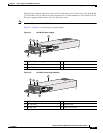
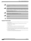
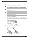
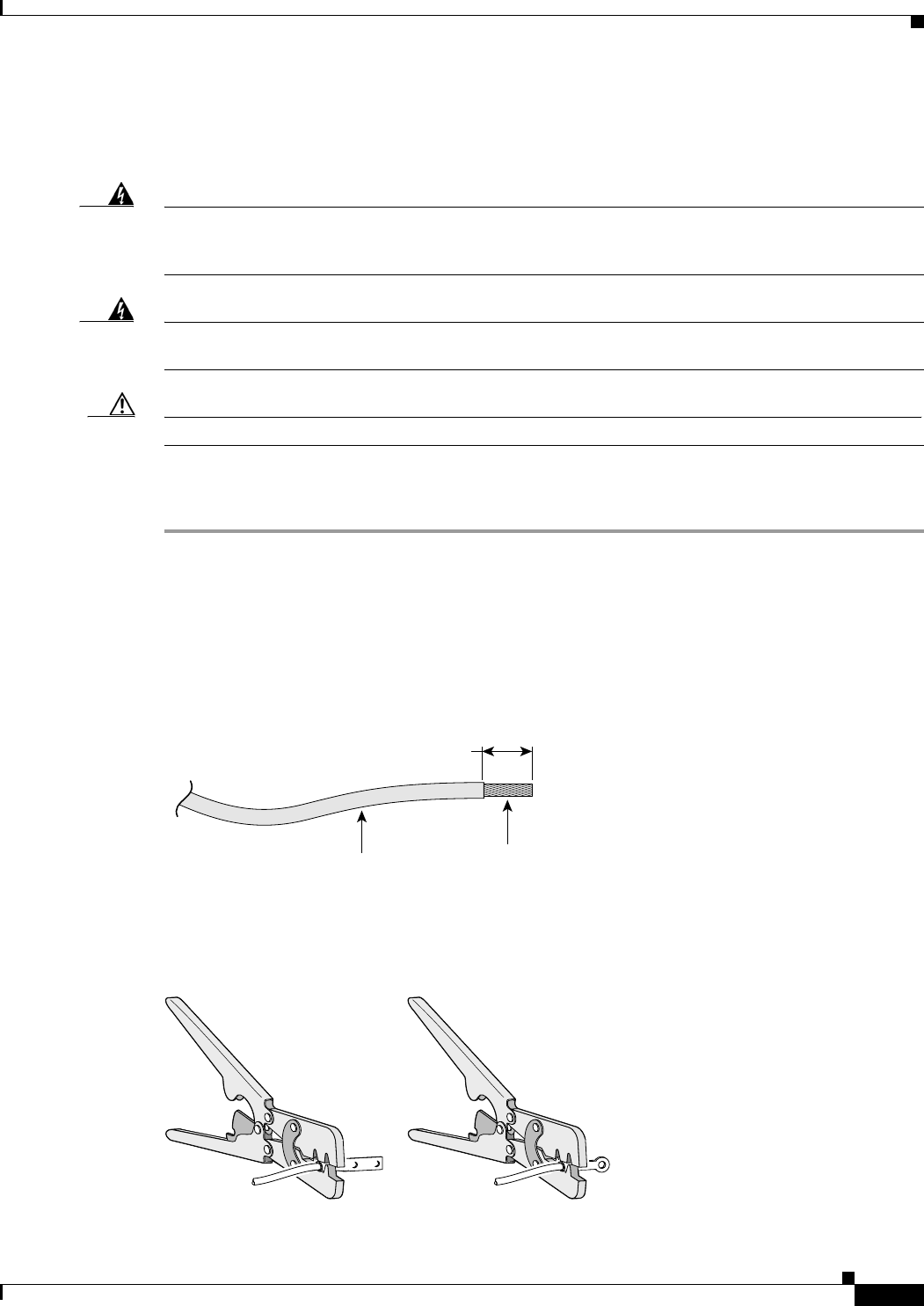
Step 2 Strip the 12-gauge or 8-gauge ground wire to 0.5 inch (12.7 mm) ± 0.02 inch (0.5 mm) (Figure 3-8).
Stripping more than the recommended amount of wire can leave exposed wire from the connector. Use
12-gauge copper ground wire for the single-ground connection. Use 8-gauge copper ground wire for the
dual-ground connection.
Figure 3-8 Stripping the Ground Wire
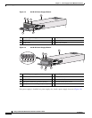
Step 3 Slide the open end of the ground lug over the exposed area of the wire.
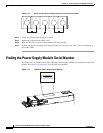
Step 4 Using a Panduit crimping tool, crimp the ground lug to the wire (Figure 3-9).
Figure 3-9 Crimping the Ground Lug
Insulation
Wire lead
0.5 in. (12.7 mm)
±
0.02 in. (0.5 mm)
60528
200044