


2-5
Catalyst 3750-X and 3560-X Switch Hardware Installation Guide
OL-19593-01
Chapter 2 Switch Installation
Data Stack Cabling Configurations
Switch Data Stacking Guidelines
For general concepts and management procedures for switch stacks, see the switch software
configuration guide on Cisco.com. When adding a Catalyst
3750-X switch to a Catalyst 3750 switch
stack, review the Catalyst 3750-X Switch Stack Compatibility Guide on Cisco.com for information about
mixed stack configurations.
Before connecting the switches in a stack, keep in mind these stacking guidelines:
• Size of the switch and any optional power-supply module. The 1100-W power-supply module is
longer than the other modules. Stacking switches with the same power-supply modules together
makes it easier to cable the switches. For switch dimensions, see
Appendix A, “Technical
Specifications.”
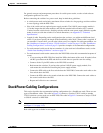
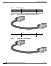
• Length of cable. Depending on the configurations that you have, you might need different-sized
cables. If you do not specify the length of the StackWise cable, the 0.5-meter cable is supplied. If
you need the 1-meter cable or the 3-meter cable, you can order it from your Cisco supplier. For cable
part numbers, see the
“StackWise Ports” section on page 1-16. The “Data Stack Cabling
Configurations” section on page 2-5 provides examples of recommended configurations.
• For rack-mounted switch stacks connected to the XPS-2200, review this recommended sequence of
events:
–
If you are using the XPS-2200, install the XPS first at the bottom of the stack. If needed, allow
one RU space between the XPS and the first switch above to provide room for cabling.
–
Connect the 12-pin XPS cables to the XPS-2200.
–
Rack-mount the switches. If you have the optional 1100-W power-supply module, first mount
the switch before installing the power-supply module.
–
Connect the XPS cable to the first switch above the XPS-2200. Connect the stack cables to the
first switch above the XPS.
–
Connect the XPS cable to the second switch above the XPS-2200. Connect the stack cables to
the next switch above the XPS.
–
Repeat until all switches are connected.
• For rack-mounted switch stacks that are members of a StackPower stack as well as a data stack, see
the
“Planning a StackPower Stack (Catalyst 3750-X Switches)” section on page 2-8.
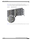
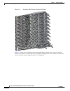
Data Stack Cabling Configurations
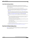
Figure 2-1 is an example of a recommended configuration that uses the supplied 0.5-meter StackWise
cable. In this example, the switches are stacked in a vertical rack or on a table. This configuration
provides redundant connections.