2-9
Cisco Aironet 1550 Series Outdoor Mesh Access Point Hardware Installation Guide
OL-24247-01
Chapter 2 Installing the Access Point
Installation Guidelines
• Data rates—Sensitivity and range are inversely proportional to data bit rates. The maximum radio
range is achieved at the lowest workable data rate. A decrease in receiver sensitivity occurs as the
radio data increases.
• Antenna type and placement—Proper antenna configuration is a critical factor in maximizing radio
range. As a general rule, range increases in proportion to antenna height. However, do not place the
antenna higher than necessary, because the extra height also increases potential interference from
other unlicensed radio systems and decreases the wireless coverage from the ground.
• Physical environment—Clear or open areas provide better radio range than closed or filled areas.
• Obstructions—Physical obstructions such as buildings, trees, or hills can hinder performance of
wireless devices. Avoid locating the devices in a location where there is an obstruction between the
sending and receiving antennas.
Before Beginning the Installation
Before you begin the installation process:
• Ensure that a site survey has been performed.
• Ensure that your network infrastructure devices are operational and properly configured.
• Ensure that your controllers are connected to switch trunk ports.
• Ensure that your switch is configured with untagged access ports for connecting your access points.
• Ensure that a DHCP server with Option 43 configured is reachable by your access points, or
manually configure the controller information in the access point (for additional information, refer
to the “Configuring DHCP Option 43” section on page F-1).
• Become familiar with the access point installation components (see the “Becoming Familiar with
Access Point Installation Components” section on page 2-9).
Becoming Familiar with Access Point Installation Components
The access point is designed to be installed in an outdoor environment, such as the exterior roof overhang
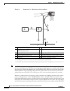
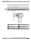
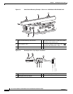
of a tall building or a streetlight pole. Carefully review the following figures to become familiar with the
system components, connectors, indicators, cables, system interconnection, and grounding:
• Components in a typical access point installation (see Figure 2-1)
• Pole mount installation (see Figure 2-2)
• Cable strand mount installation (see Figure 2-3)
• Streetlight power tap installation (see Figure 2-4)
Note The illustrations in this document show all available connections for the access point. Unused
connections are capped with a connector plug to ensure the watertight integrity of the access point,
except for the AC power entry connector on the 1552E access point. Liquid-tight adapters are provided
for connector openings, which can be installed before or after deploying the access point.
When not using the AC input connector to power the 1552E (for example when powering using the Cisco
power injector), it is important to cover the AC power entry connector. The correct cap is Remke part
number 75-0086 (http://www.remke.com/).


