


3-3
C7200 VSA (VPN Services Adapter) Installation and Configuration Guide
OL-9129-02
Chapter 3 Removing and Installing the VSA
VSA Removal and Installation
Follow these steps to remove and insert the VSA in the Cisco 7200VXR series routers:
Step 1 Turn the power switch to the off position and then remove the power cable. (Optional on Cisco 7200VXR
series routers; see Warnings and Cautions, page 3-2, above.)
Step 2 Attach an ESD wrist strap between you and an unpainted chassis surface.
Step 3 Unscrew the screws holding the VSA in the slot.
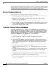
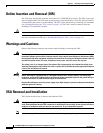
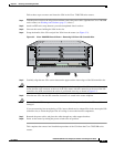
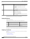
Step 4 Grasp the handle of the VSA and pull the VSA from the router (see Figure 3-2).
Figure 3-2 Cisco 7206VXR Chassis Shown - Removing VSA from I/O Controller Slot
Step 5 Carefully align the new VSA carrier between the upper and the lower edges of the I/O controller slot.
Caution To prevent jamming the carrier between the upper and the lower edges of the I/O controller slot, and to
ensure that the edge connector at the rear of the VSA mates with the connection at the rear of the I/O
controller slot, make certain that the carrier is positioned correctly, as shown in Figure 3-2.
Step 6 Slide the new VSA into the I/O controller slot until it is seated in the router midplane.
Caution Do not allow the VSA components to come in contact with the system board or the VSA could be
damaged.
If you are removing, but not replacing a VSA, insert a blank service adapter filler in the unoccupied I/O
controller slot, to ensure the proper flow of cooling air across the internal components.
Step 7 Reattach the power cable, and place the cable through any cable support brackets.
Step 8 Power on the router by turning the power switch to the on position.
This completes the removal and installation procedure of the VSA from the Cisco 7200VXR series
routers.
153077
3
1
5
Cisco 7200
Series VXR
2
4
6
0
C7200-VSA