


10
Cisco Connected Grid Modules for CGR 1000 Series—WiMAX Installation and Configuration Guide
OL-26236-03
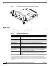
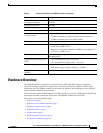
Hardware Overview
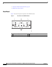
Radio Frequency Interface
The Radio Frequency (RF) interface consists of two QMA connectors on the faceplate labeled MAIN and
AUX. Both antennas are mandatory; it both transmits and receives RF. The second AUX QMA connector
is for the optional RX Diversity.
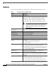
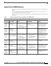
DC Power Consumption
The average DC power consumption according to the duty cycle is as follows:
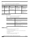
Temperature Monitoring State Machine
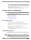
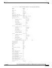
The state machine in the WiMAX module monitors the embedded module temperature. The command
show environment temperature shows the module temperature in Celsius. For example, the
temperature sensor of the WIMAX module shows as 46-degrees Celsius.
# show module
Mod Ports Module-Type Model Status
--- ----- ----------------------------------- ------------------ ----------
1 0 CGR1000 Supervisor Module CGR1120/K9 active *
2 9 CGR1000 Ethernet Module CGR1000 ok
3 1 Connected Grid Module - IEEE 802.16 CGM-WIMAX-1.8GHZ ok
4 1 Connected Grid Module - IEEE 802.15 CGM-WPAN-FSK-NA ok
# sh environment temperature
Temperature:
--------------------------------------------------------------------
Module Sensor MajorThresh MinorThres CurTemp Status
(Celsius) (Celsius) (Celsius)
--------------------------------------------------------------------
1 Sensor0 75 60 44 Ok
3 Sensor0 75 60 46 Ok
4 Sensor0 75 60 46 Ok
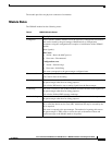
Module Power States
The module has the following power states:
• Normal mode—Module is active. Receive and Transmit modes are possible. In this state:
–
The module is fully powered.
–
The module is capable of placing/receiving calls or establishing data connections on the
wireless network.
–
The USB interface is fully active.
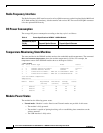
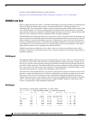
Table 6 Power Specifications WiMAX 1.8 MHz Module
Transmit Duty Cycle
(Tx/Rx) 1 Transmit Spatial Stream 2 Transmit Spatial Streams
40%/60% 3.7 W 5.3 W