


4-3
Cisco ONS 15454 SDH Procedure Guide, R4.6
January 2004
Chapter 4 Turn Up Node
NTP-D24 Verify Card Installation
Step 6 Verify that electrical cards (E1-N-14, E1-42, E3-12, DS3I-N-12, or STM1E) are installed in the
ONS 15454 SDH slots as designated by your installation plan.
Step 7 If your site plan requires an Ethernet card, verify that the Ethernet card is installed in the specified slot
and its ACT (active) LED displays a solid green light:
• The E100T-12, E100T-12-G, E1000-2, and E1000-2-G cards are installed in Slots 1 to 6 or 12 to 17
• The G1000-4 cards are installed in Slots 1 to 4 or 14 to 17.
• The G1K-4, ML1000-2, and ML100T-12 cards can be installed in Slots 1 to 6 or 12 to 17 if an
XC10G cross-connect is installed. However, they must be installed in Slots 5, 6, 12, or 13 if XC or
XCVT cards are installed.
Step 8 If Ethernet cards are installed, verify that the correct cross-connect cards are installed in Slots 8 and 10:
• E100T-12-G, E1000-2-G, and G1000-4 cards require XC10G cards.
• G1K-4, ML1000-2, and ML100T-12 cards require XC10G cards if they are installed in Slots 1 to 4
or 14 to 17.
Step 9 If an E1000-2, E1000-2-G, G1000-4, G1K-4, or ML1000-2 Ethernet card is installed, verify that it has
a gigabit interface converter (GBIC) or SFP installed. If not, see the “DLP-D335 Install GBIC or SFP
Connectors” task on page 2-20.
Step 10 Verify that STM-N cards (STM-1, STM-1-8, STM-4, STM-4-4, STM-16, STM-16 any slot (AS), and
STM-64) are installed in the slots designated by your site plan. STM-1, STM-4, and STM-16AS cards
can be installed in Slots 1-6 or 12-17. The STM-1-8 and STM-4-4 can only be installed in Slots 1 to 4
or 14 to 17, and the STM-16 and STM-64 can only be installed in Slots 5 to 6 and 12 to 13.
Step 11 Verify that all installed STM-N cards display a solid amber STBY LED.
Step 12 If transponder or muxponder cards are installed (T XP_MR_10G, MXP_2.5G_10G, TXP_MR_2.5, or
TXPP_MR_2.5G), verify that they are installed in Slots 1 to 6 or 12 to 17 and GBIC or SFP connectors
are installed. If GBIC or SFP connectors are not installed, complete the “DLP-D335 Install GBIC or SFP
Connectors” task on page 2-20.
Step 13 If Fibre Channel cards (FC_MR-4) are installed, verify that the FC_MR-4 is installed in Slots 1 to 6 or
12 to 17 and displays a solid green ACT (Active) LED.
Step 14 Verify that fiber-optic cables are installed and connected to the locations indicated in the site plan. If the
fiber-optic cables are not installed, complete the “NTP-D19 Install Fiber-Optic Cables on STM-N
Cards” procedure on page 2-30.
Step 15 Verify that fiber is routed correctly in the shelf assembly and fiber boots are installed properly. If the
fiber is not routed on the shelf assembly, complete the “NTP-D245 Route Fiber-Optic Cables” procedure
on page 2-56. If the fiber boots are not installed, complete the “DLP-D45 Install the Fiber Boot” task on
page 2-39.
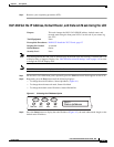
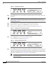
Step 16 Verify that the software release shown on the LCD matches the software release indicated in your site
plan. If the release does not match, perform one of the following procedures:
• Perform a software upgrade using a Cisco ONS 15454 SDH software CD. Refer to the
Cisco ONS 15454 SDH Software Upgrade Guide for instructions.
• Replace the TCC2 cards with cards containing the correct release. Refer to the
Cisco ONS 15454 SDH Troubleshooting Guide.
Step 17 Continue with the “NTP-D30 Create Users and Assign Security” procedure on page 4-4.
Stop. You have completed this procedure.