


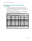


Initial Power Up, Calibration, and Registration (AC Power applied)
4021194 Rev A 97
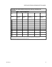
Front Panel LED Status Indicators During Initial Power Up, Calibration, and
Registration
Part 2, Telephone Registration
Step:
7
8
9
10
11
Front Panel
Indicator
Data Network
Registration
Complete
Requesting
Telephone IP
Address
Request
Telephone
Provisioning File
Restarting Voice
Service
Telephone
Registration
Complete
1
POWER
On
On
On
On
On
2
DS
On
On
On
On
On
3
US
On
On
On
On
On
4
ON-LINE
On
On
On
On
On
5
PC*
On
On
On
On
On
6
WLAN*
On or Blinking
On or Blinking
On or Blinking
On or Blinking
On or Blinking
7
WLANSETU
P
Off or Blinking
Off or Blinking
Off or Blinking
Off or Blinking
Off or Blinking
8
LINE1
Off
Blinking
Off
Blinking
On
9
LINE2
Off
Off
Blinking
Blinking
On
*Notes:
PC indicator displays only when a PC device is connected to the Ethernet port on the gateway.
WLAN indicator displays only when WLAN is turned on.