


Send document comments to nexus3k-docfeedback@cisco.com
D-2
Cisco Nexus 3000 Series Hardware Installation Guide
OL-25338-04
Appendix D LED Descriptions
Chassis and Module LEDs for the Cisco Nexus 3000 Series Switches
Chassis and Module LED Descriptions
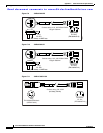
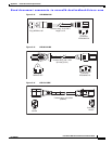
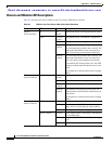
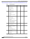
Table D-1 describes the chassis LEDs for the Cisco Nexus 3000 Series switches.
Ta b l e D-1 LEDs for the Cisco Nexus 3000 Series Fabric Extenders
Component LED Status Description
Chassis
(front and back)
ID On
(blue)
Identifies the chassis receiving the beacon signal.
Status Solid on
(green)
All diagnostics pass. The module is operational.
Off The module is not receiving power.
On
(amber)
The module is booting or running diagnostics.
An overtemperature condition has occurred. The
temperature threshold has been exceeded by a
small value during environmental monitoring.
Blinking
(amber)
An overtemperature condition has occurred. The
temperature threshold has been exceeded by a
large value during environmental monitoring.
If the module fails during initial reset, the LED
continues to blink and the module does not come
online.
The module has a runtime failure and is brought
offline.
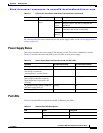
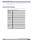
Fan tray
(front of chassis)
Status Solid on
(green)
All diagnostics pass. The module is operational.
Off The module is not receiving power.
Solid on
(amber)
The module is booting or running diagnostics.
Blinking
(amber)
If the module fails during an initial reset, the
LED continues to blink and the module does not
come online.
The module has a runtime failure and is brought
offline.
Power supply
(front of chassis)
OK (green) Solid on Power supply is on and okay.
Blinking 3.3 voltage standby (VSB) is on but the power
supply unit is not powering the other modules.
Off No AC power to the power supply.
FAULT (amber) Solid on Power supply failure, overvoltage, overcurrent,
or overtemperature.
Blinking AC is present, 3.3 VSB on, and the power supply
is off.
Off Operating normally.