


Send document comments to nexus3k-docfeedback@cisco.com
4-4
Cisco Nexus 3000 Series Hardware Installation Guide
OL-25338-04
Chapter 4 Replacing Components
Replacing a Fan Tray
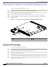
Installing a DC Power Supply
In a system with dual power supplies, connect each power supply to a separate power source. If a power
source failure occurs, the second source will most likely still be available.
Caution Be sure that the power supply that you are installing has the same airflow direction as the fan tray module
and the other power supply. Either all of the modules must have front-to-back airflow (no black stripe
on the front of the module) or all of the modules must have back-to-front airflow (black stripe on the
front of the module). If the modules have different airflow directions in the same chassis, you will see
an error message.
To install a DC power supply, follow these steps:
Step 1 Verify that the DC power is off at the circuit breaker.
Step 2 Ensure that the system (earth) ground connection has been made for the chassis. For ground connection
instructions, see the
“Grounding the Switch” section on page 2-10.
Step 3 If the power supply bay has a filler panel, push and hold the thumb latch to the left, and then slide the
filler panel out of the power supply bay.
Step 4 Hold the replacement power supply by the handle and position it so that the thumb latch is on the right,
and then slide it into the power supply bay, ensuring that the power supply is fully seated in the bay.
Step 5 Engage the thumb latch so that the power supply is firmly held in place in its slot.
Step 6 If there is a clear plastic cover that prevents your access to the terminals, unclip it and remove it from
the chassis.
Step 7 Fasten the negative cable to the left terminal.
Note On early manufactured power supplies, the left terminal is labeled as +. On currently
manufactured power supplies, the left terminal is labeled as -.
Step 8 Fasten the positive cable to the right terminal.
Note On early manufactured power supplies, the right terminal is labeled as -. On currently
manufactured power supplies, the right terminal is labeled as +.
Step 9 Clip the clear plastic cover over the terminals to prevent accidental touching of the terminals.
Step 10 Turn on the power at the circuit breaker.
Step 11 Verify the power supply operation by checking that the power supply LED is green. For information
about what the power supply LEDs indicate, see the
“Power Supply Status” section on page D-3.
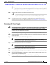
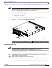
Replacing a Fan Tray
The fan tray is designed to be removed and replaced while the system is operating without causing an
electrical hazard or damage to the system if the replacement is performed within 1 minute.