


Send document comments to nexus3k-docfeedback@cisco.com
2-3
Cisco Nexus 3000 Series Hardware Installation Guide
OL-25338-04
Chapter 2 Installing the Cisco Nexus 3000 Series Switches
Preparing for Installation
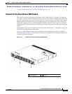
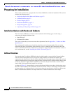
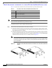
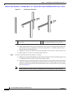
Figure 2-1 Distinguishing Between Chassis with Forward and Reverse Airflow
Chassis Weight
When lifting the switch chassis, follow these guidelines:
• Disconnect all power and external cables before lifting the switch.
• Ensure that your footing is solid and the weight of the switch is evenly distributed between your feet.
• Lift the switch slowly, keeping your back straight. Lift with your legs, not with your back. Bend at
the knees, not at the waist.
Installation Guidelines
When installing the Cisco Nexus 3000 Series switch, follow these guidelines:
• Record the information listed in Appendix E, “Site Planning and Maintenance Records” as you
install and configure the switch.
• Ensure that there is adequate space around the switch to allow for servicing the switch and for
adequate airflow (
Appendix B, “Technical Specifications” lists the service and airflow
requirements).
• Ensure that the air-conditioning meets the heat dissipation requirements listed in Appendix B,
“Technical Specifications.”
• Ensure that the switch is going to be positioned so that it takes in air from a cold aisle and exhausts
air to the hot aisle. If there is a black stripe across the front of these modules, they have forward
airflow and must be positioned with the fan tray and power supplies in a cold aisle. If there is a black
stripe across the front of these modules, they have reverse airflow and must be positioned with the
port connections in a cold aisle.
• Ensure that the cabinet or rack meets the requirements listed in Appendix A, “Cabinet and Rack
Specifications.”
Note Jumper power cords are available for use in a cabinet. See the “Jumper Power Cord” section on
page C-8.
• Ensure that the chassis can be adequately grounded. If the switch is not mounted in a grounded rack,
we recommend connecting both the system ground on the chassis and the power supply ground
directly to an earth ground.
1 No black stripe indicates forward airflow. 2 Black stripe indicates reverse airflow.