


Send document comments to nexus3k-docfeedback@cisco.com
4-3
Cisco Nexus 3000 Series Hardware Installation Guide
OL-25338-04
Chapter 4 Replacing Components
Replacing a Power Supply
Note Depending on the outlet receptacle on your power distribution unit, you may need the optional
jumper power cord to connect the Cisco Nexus 3000 Series switch to your outlet receptacle. See
the “Jumper Power Cord” section on page C-8.
Step 5 Connect the other end of the power cable to an AC power source.
Caution In a system with dual power supplies, connect each power supply to a separate power source.
If a power source failure occurs, the second source will most likely still be available.
Step 6 Verify that the power supply is operational by checking that the power supply LED is green. For
information about what the power supply LEDs indicate, see the
Appendix D, “LED Descriptions.”
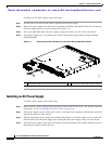
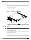
Removing a DC Power Supply
Caution If the switch has only one DC power supply, removing the power supply causes the device to shut down.
If you are using two power supplies and you remove one of them, the switch continues to operate.
To remove a DC power supply, follow these steps:
Step 1 Shut off the DC power to the power supply at the circuit breaker. Verify that both LEDs are off.
Step 2 Unclip and remove the clear plastic cover that prevents access to the positive and negative terminals on
the DC power supply.
Step 3 Unfasten the positive power cable from the right terminal.
Note On early manufactured power supplies, the right terminal is labeled as -. On currently
manufactured power supplies, the right terminal is labeled as +.
Step 4 Unfasten the negative power cable from the left terminal.
Note On early manufactured power supplies, the left terminal is labeled as +. On currently
manufactured power supplies, the left terminal is labeled as -.
Step 5 Replace the clear plastic cover that prevents access to the terminals.
Step 6 Press the thumb latch to disengage the power supply from the chassis and use the handle to pull it part
way out of the chassis.
Step 7 Place your other hand under the power supply to support it while you slide it out of the chassis. Place
the power supply on an antistatic surface.
Step 8 If the power supply bay is to remain empty, install a blank power supply filler panel.