


1-2
Cisco ME 3400E Ethernet Access Switch Hardware Installation Guide
OL-16447-01
Chapter 1 Product Overview
Front Panel
Front Panel
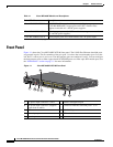
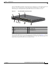
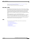
Figure 1-1 shows the Cisco ME 3400E-24TS-M front panel. The 10/100 Fast Ethernet downlink ports
are grouped in pairs. The first member of the pair (port 1) is above the second member (port 2) on the
left. Port
3 is above port 4, and so on. The dual-purpose ports are numbered 1 and 2. You can configure
the dual-purpose ports as either copper-based 10/100/1000 ports or as fiber-optic SFP-module ports. See
the
“SFP Modules” section on page 1-5 for more information.
Figure 1-1 Cisco ME 3400E-24TS-M Front Panel
Table 1-1 Cisco ME 3400E Models and Descriptions
Switch Model Description
Cisco ME 3400E-24TS-M 24 10/100 FastEthernet downlink ports and 2 dual-purpose ports
(2 10/100/1000BASE-T copper ports and 2 SFP
1
module slots);
supports removable AC- and DC-power supplies.
1. SFP = small form-factor pluggable.
Cisco ME 3400EG-12CS-M 12 dual-purpose ports and 4 SFP-module slots; supports removable
AC- and DC-power supplies.
Cisco ME 3400EG-2CS-A 2 dual-purpose ports and 2 SFP-module slots, AC-power input.
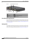
1 AC-power input connectors 1 and 2 6 Ethernet management port
2 DC-power input connectors (supports
power feeds A and B)
7 10/100 Fast Ethernet downlink ports 1 to 24
3 LEDs 8 10/100/1000 ports
4 Alarm input port 9 SFP-module slots
5 Console port
280816
3
5
4
1
8
9
7
2
6