


3-13
Cisco ME 3400E Ethernet Access Switch Hardware Installation Guide
OL-16447-01
Chapter 3 Installing and Removing AC- and DC-Power-Supply Modules
Power-Supply Module Installation
Step 1 To ensure that all power is OFF, locate the circuit breaker on the panel board that services the DC circuit,
switch the circuit breaker to the OFF position, and tape the switch handle of the circuit breaker in the
OFF position.
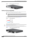
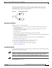
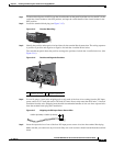
Step 2 Locate the terminal block plug (see Figure 3-15).
Figure 3-15 Terminal Block Plug
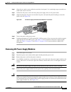
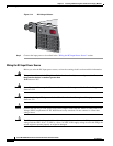
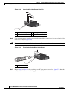
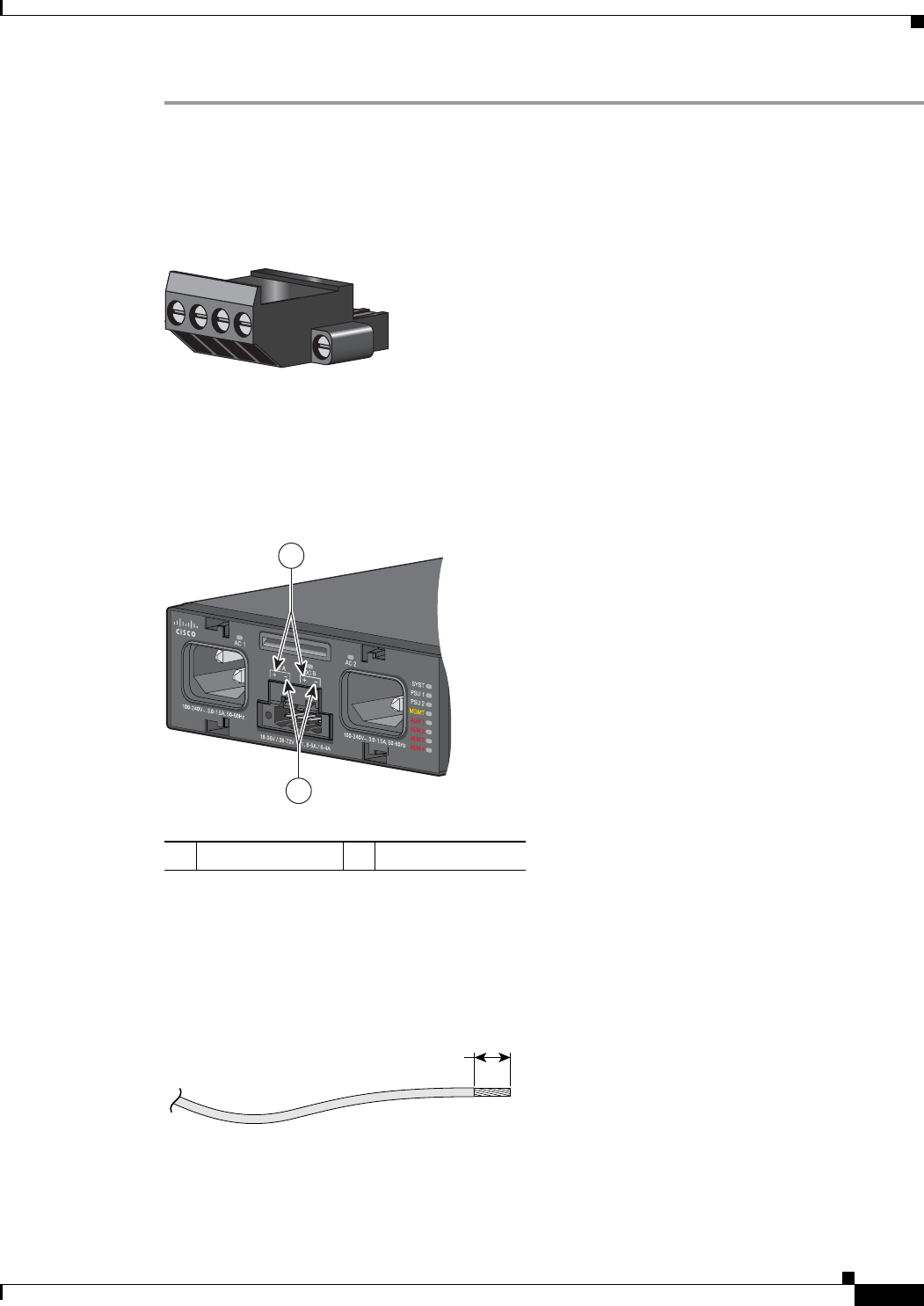
Step 3 Identify the positive and negative feed positions for the terminal block connection. The wiring sequence
is positive to positive and negative to negative for both the A and the B feed wires.
The switch front panel shows the positive and negative positions for both the A and B feed wires. (See
Figure 3-16.)
Figure 3-16 Positive and Negative Positions
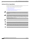
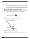
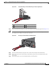
Step 4 Use an 18-gauge (1 mm) wire-stripping tool to strip each of the four wires coming from the DC-input
power source to 0.27 inch (6.6 mm) ± 0.02 inch (0.5 mm). Do not strip more than 0.29 inch (7.4 mm) of
insulation from the wire. Stripping more than the recommended amount of wire can leave exposed wire
from the terminal block plug after installation.
Figure 3-17 Stripping the DC-Input Power Source Wire
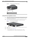
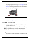
Step 5 Insert the exposed wire of one of the four DC-input power source wires into the terminal block plug.
Make sure that you cannot see any wire lead. Only wire with insulation should extend from the terminal
block.
280941
1 Positive position 2 Negative position
1
280942
2
0.25 in. (6.3 mm)
±
0.02 in. (0.5 mm)
60531