


2-20
Cisco ME 3400E Ethernet Access Switch Hardware Installation Guide
OL-16447-01
Chapter 2 Switch Installation
Installing and Removing SFP Modules
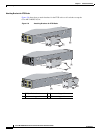
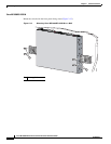
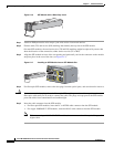
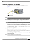
Figure 2-16 SFP Module with a Bale-Clasp Latch
Step 1 Attach an ESD-preventive wrist strap to your wrist and to a bare metal surface.
Step 2 Find the send (TX) and receive (RX) markings that identify the top side of the SFP module.
On some SFP modules, the send and receive (TX and RX) markings might be replaced by arrows that
show the direction of the connection, either send or receive (TX or RX).
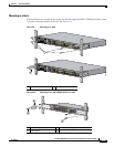
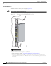
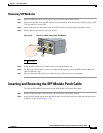
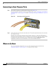
Step 3 Align the SFP module in front of the slot opening and push until you feel the connector on the module
snap into place in the rear of the slot (see Figure 2-17).
Figure 2-17 Installing an SFP Module into an SFP Module Slot
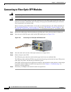
Step 4 For fiber-optic SFP modules, remove the dust plugs from the optical ports, and store them for later use.
Caution Do not remove the dust plugs from the fiber-optic SFP module port or the rubber caps from the
fiber-optic cable until you are ready to connect the cable. The plugs and caps protect the SFP module
ports and cables from contamination and ambient light.
Step 5 Insert the cable connector into the SFP module:
• For fiber-optic SFP modules, insert the LC or MT-RJ cable connector into the SFP module.
• For copper 1000BASE-T SFP modules, insert the RJ-45 cable connector into the SFP module.
Note When connecting to 1000BASE-T SFP modules, be sure to use a twisted four-pair, Category 5 or
higher cable.
86575
280844