


3-15
Cisco ME 3400E Ethernet Access Switch Hardware Installation Guide
OL-16447-01
Chapter 3 Installing and Removing AC- and DC-Power-Supply Modules
Power-Supply Module Installation
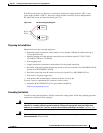
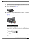
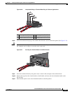
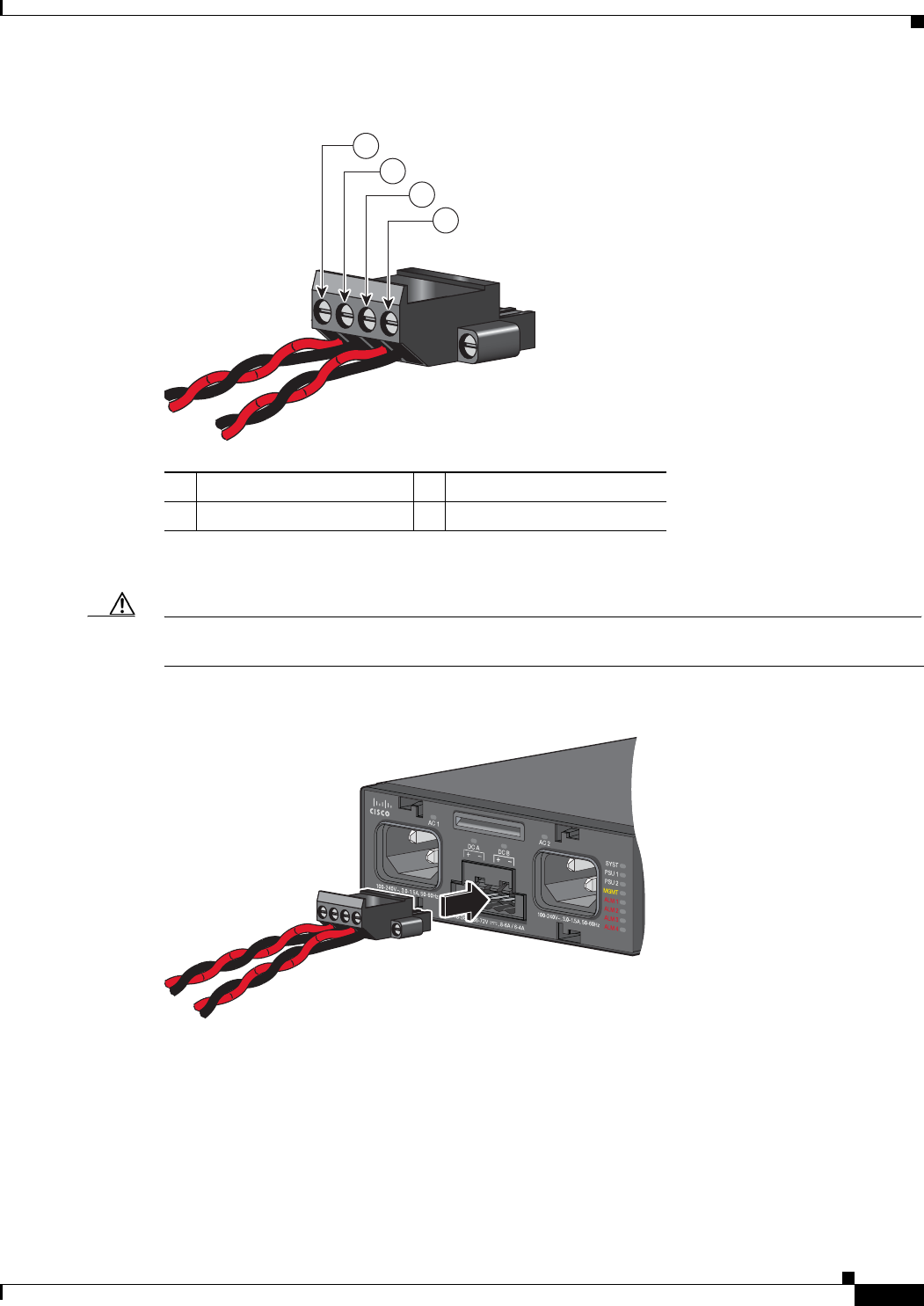
Figure 3-20 Completed Wiring of Terminal Block Plug for Telecom Applications
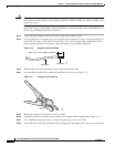
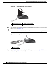
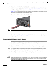
Step 8 Insert the terminal block plug in the terminal block header on the switch front panel. (See Figure 3-21).
Caution Secure the wires coming in from the terminal block so that they cannot be disturbed by casual contact.
For example, use tie wraps to secure the wires to the rack.
Figure 3-21 Inserting the Terminal Block in the Block Header
Step 9 Secure the terminal block by using the screws on the far left and right of the terminal block.
Step 10 Remove the tape from the circuit-breaker switch handle, and move the circuit-breaker handle to the
ON position.
Step 11 Move the DC-power source circuit-breaker handles to the ON position.
1
Return (positive) Feed A 3 Return (positive) Feed B
2 Supply (negative) Feed A 4 Supply (negative) Feed B
280945
1
2
3
4
280946