


3-10
Cisco ME 3400E Ethernet Access Switch Hardware Installation Guide
OL-16447-01
Chapter 3 Installing and Removing AC- and DC-Power-Supply Modules
Power-Supply Module Installation
Caution To make sure that the equipment is reliably connected to earth ground, follow the grounding
procedure instructions, and use a UL-listed lug suitable for number-6 AWG wire and two number-10-32
ground-lug screws.
Follow these steps to install either a single-ground lug or a dual-ground lug on the switch. Make sure to
follow any grounding requirements at your site.
Step 1 Locate the ground adaptor and the dual-hole lug that ships with the switch.
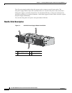
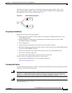
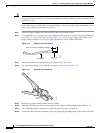
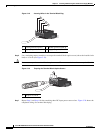
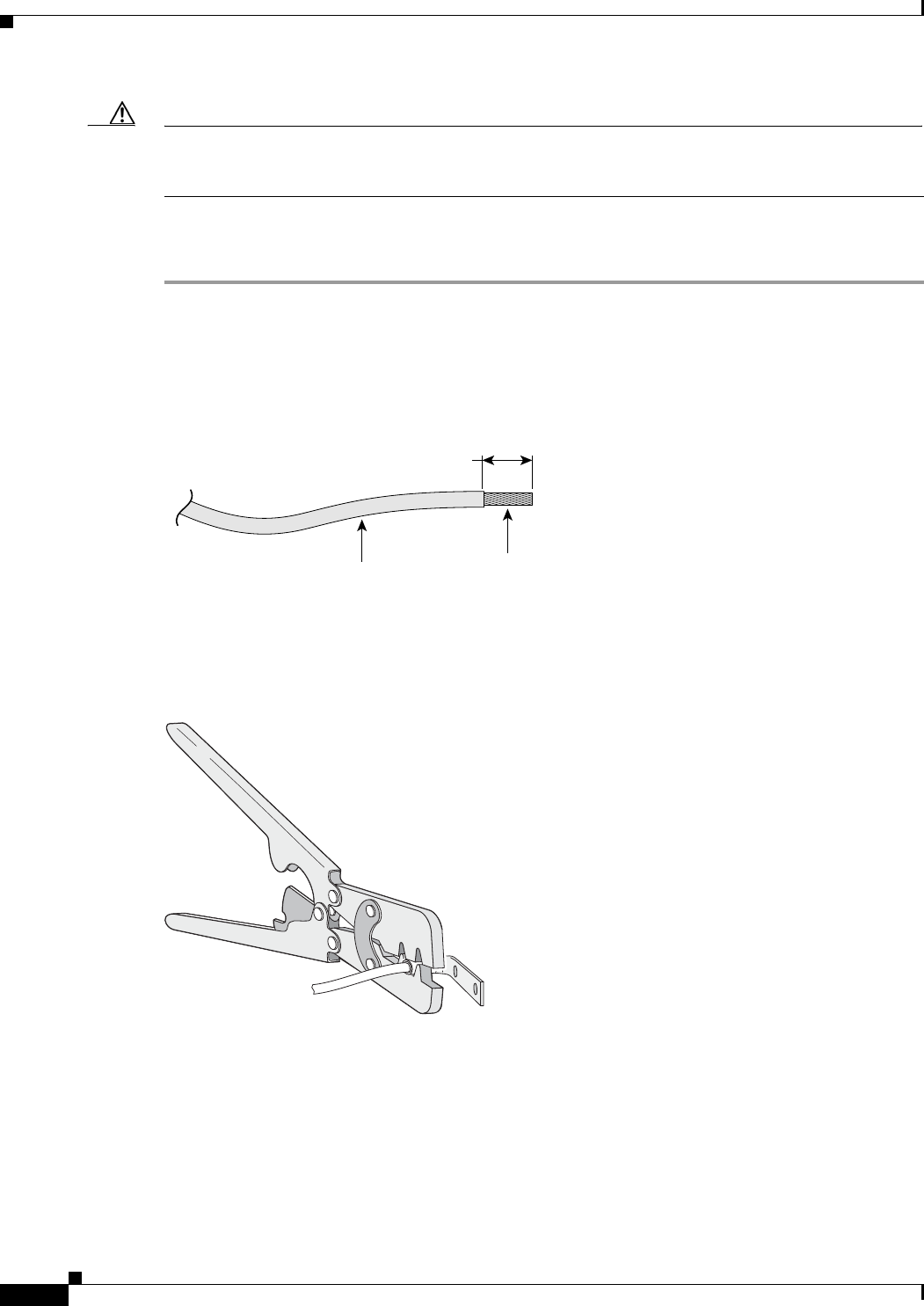
Step 2 If your ground wire is insulated, use a wire stripping tool to strip the 12-gauge or 6-gauge ground wire
to 0.5 inch (12.7 mm) ± 0.02 inch (0.5 mm) (Figure 3-10). Use 12-gauge copper ground wire for the
single-ground connection. Use 6-gauge copper ground wire for the ground connection.
Figure 3-10 Stripping the Ground Wire
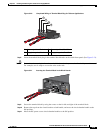
Step 3 Slide the open end of the ground lug over the exposed area of the wire.
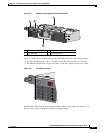
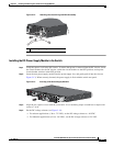
Step 4 Use a Panduit crimping tool to crimp the ground lug to the wire (see Figure 3-11).
Figure 3-11 Crimping the Ground Lug
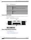
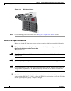
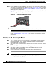
Step 5 Remove the ground screw from the switch rear panel.
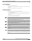
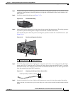
Step 6 Attach the dual-hole lug and the wire assembly to the adaptor with the supplied nuts (Figure 3-12).
Step 7 Use a ratcheting torque screwdriver to torque the ground-lug screws to 60 in-lb.
Step 8 Connect the other end of the grounding wire to an appropriate grounding point at your site or to the rack.
Insulation
Wire lead
0.5 in. (12.7 mm)
±
0.02 in. (0.5 mm)
60528
280938