


1-4
Cisco ME 3400E Ethernet Access Switch Hardware Installation Guide
OL-16447-01
Chapter 1 Product Overview
Front Panel
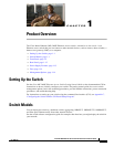
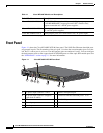
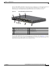
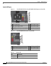
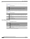
Figure 1-3 Cisco ME 3400EG-2CS-A Front Panel
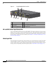
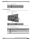
AC- and DC-Power Input Connectors
The Cisco ME 3400E-24TS-M and the Cisco ME 3400EG-12CS support combinations of power-supply
modules: two AC, two DC, or one AC and one DC. The two AC- and one DC-power connectors on the
front panel accommodate the mixture of AC- and DC-power-supply modules. The DC-power connector
has the standard A and B feeds for DC redundancy. See
Chapter 3, “Installing and Removing AC- and
DC-Power-Supply Modules.”
Alarm Input Port
The switch supports four alarm inputs. The alarm input is a dry-contact alarm port. Use the CLI to define
each alarm input to respond to a normally open or closed dry-contact closure and to define the alarm
severity as minor, major, or critical. When a condition triggers an alarm, the console displays an alarm
message, and the corresponding Alarm LED responds (see the
“Alarm LEDs” section on page 1-11).
1 LEDs 5 Air intake vents
2 Alarm input port 6 10/100/1000 ports
3 Console port 7 Gigabit Ethernet SFP-module slots
4 Ethernet management port 8 SFP-module slots
2
808
1
8
2
6
1
3
4
7
5
8