


1-7
PA-POS-1OC3 Single-Port Port Adapter Installation and Configuration Guide
OL-6514-04
Chapter 1 PA-POS-1OC3 Overview
Cables and Connectors
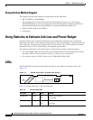
After system initialization, the ENABLED LED comes on to indicate that power is received and that the
PA-POS-1OC3 port adapter is enabled for operation.
The following conditions must all be met before the PA-POS-1OC3 is enabled:
• The PA-POS-1OC3 is correctly connected and receiving power.
• The host system software supports the PA-POS-1OC3.
If any of these conditions are not met, or if the initialization fails, the ENABLED LED does not come on.
Cables and Connectors
Use single-mode (for intermediate- or long-reach configurations) or multimode optical fiber cable to
connect your router to a network or to connect two OC-3-equipped routers back-to-back.
Note Long-range SFP optics modules (for long-reach configurations) cannot be connected
back-to-back without using an attenuator between the two of them.
The PA-POS-1OC3 provides the following optical fiber options:
• Multimode—155 Mbps, OC-3 optical fiber (SONET STS-3c or SDH STM-1)
Use a multimode optical fiber that has a core/cladding diameter of 62.5/125 microns.
• Single-mode—155 Mbps, OC-3 optical fiber (SONET STS-3c or SDH STM-1)
Use a single-mode optical fiber that has a core/cladding diameter of 8-9/125 microns. (Nominal
diameter is approximately 10/125 microns.)
Note For maximum cable lengths between stations, see Table 1-1 on page 1-5. Single-mode and multimode
optical fiber cables for the PA-POS-1OC3 are not available from Cisco Systems; however, they are
available from commercial cable vendors.
RCV Green On
Off
Receive signal is present (a cable is attached and the link
is up)
No signal is present
Green Blinking
Off
Packets are currently being received
No signal is present
Table 1-2 PA-POS-1OC3 LEDs (continued)
LED Label Color State Function