


3-16
PA-POS-1OC3 Single-Port Port Adapter Installation and Configuration Guide
OL-6514-04
Chapter 3 Removing and Installing the PA-POS-1OC3
Replacing the SFP Optics Module
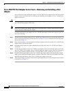
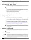
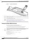
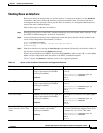
Figure 3-4 Inserting an SFP Optics Module
Step 4
Holding the module at the latching band (with your thumb and forefinger), insert the SFP optics module
into the slot on the port adapter.
Step 5 Push the module back into the slot until the latch engages. When fully inserted, only the band around the
front of the SFP optics module is visible.
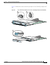
Step 6 Remove the plug from the SFP optical bores and save the plug for future use.
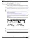
Step 7 Attach the network interface fiber-optics cable, as described in the “Cisco 7500 Series
Routers—Removing and Installing a Port Adapter” section on page 3-11.
Verifying the SFP Optics Module Installation
There are two ways that you can verify the SFP installation,
• Check the type of SFP optics module installed using the console.
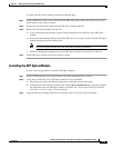
• Cable the SFP optics module and check the LEDs on the front of the PA-POS-1OC3.
Use this procedure to verify the SFP optics module installation in the PA-POS-1OC3:
Step 1 Verify the type of SFP optics module that is installed, by entering show controller pos x/y
(example: 1/0)
Step 2 Check the text in the output to verify the type of SFP that is installed.
NPE-400#show controller pos 1/0
<< omitted text >>
ipv62tag optimum fs = 0x612C6754, ipv62tagfs = 0x612C6754
SFP is TRP-03L3I1BCS OC3 SM-IR
Serial Number : 2014293
Framer is PMC PM5379 S/UNI-4x155 1 0
<< omitted text >>
89042
PA-POS-1OC3
ALARM
ENABLED
RCV
TX
RX
POS 0
CLASS 1 LASER PRODUCT
LASERPRODUKT DER KLASSE
1
PRODUIT LASER DE CLASSE
1
PRODUCTO LASER CLASE
1
122200