


3-3
PA-POS-1OC3 Single-Port Port Adapter Installation and Configuration Guide
OL-6514-04
Chapter 3 Removing and Installing the PA-POS-1OC3
Warnings and Cautions
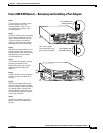
OIR Functional Description
The following is a functional description of OIR for background information only; for specific
procedures for installing and replacing a port adapter in a supported platform, refer to the “Port Adapter
Removal and Installation” section on page 3-4.
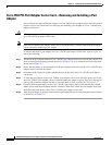
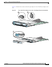
Each port adapter has a bus connector that connects it to the router. The connector has a set of tiered pins
in three lengths that send specific signals to the system as they make contact with the port adapter. The
system assesses the signals it receives and the order in which it receives them to determine if a port
adapter is being removed from or introduced to the system. From these signals, the system determines
whether to reinitialize a new interface or to shut down a disconnected interface.
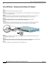
Specifically, when you insert a port adapter, the longest pins make contact with the port adapter first, and
the shortest pins make contact last. The system recognizes the signals and the sequence in which it
receives them.
When you remove or insert a port adapter, the pins send signals to notify the system of changes. The
router then performs the following procedure:
1. Rapidly scans the system for configuration changes.
2. Initializes newly inserted port adapters or administratively shuts down any vacant interfaces.
3. Brings all previously configured interfaces on the port adapter back to their previously installed
state. Any newly inserted interface is put in the administratively shutdown state, as if it were present
(but not configured) at boot time. If a similar port adapter type is reinserted into a slot, its ports are
configured and brought online up to the port count of the originally installed port adapter of that
type.
Warnings and Cautions
Observe all the warnings and cautions when installing or removing port adapters.
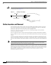
Caution Do not slide a port adapter all the way into the slot until you have connected all required cables. Trying
to do so disrupts normal operation of the router or switch.
Caution If a port adapter lever or other retaining mechanism does not move to the locked position, the port
adapter is not completely seated in the midplane. Carefully pull the port adapter halfway out of the slot,
reinsert it, and move the port adapter lever or other mechanism to the locked position.
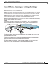
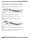
Caution To prevent jamming the carrier between the upper and the lower edges of the port adapter slot, and to
ensure that the edge connector at the rear of the port adapter mates with the connection at the rear of the
port adapter slot, make certain that the carrier is positioned correctly, as shown in the “Port Adapter
Removal and Installation” section on page 3-4.