


2-22
Cisco AC/DC Power System User Guide, R1.0
May 2006
Chapter 2 System Installation
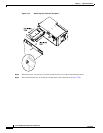
2.4.1 Install the Alarm Cable
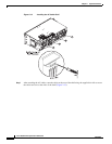
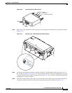
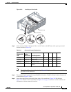
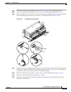
Figure 2-19 Removing the Controller Faceplate
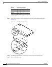
Step 2 Slide the drawer out and away from the system shelf to access the alarm interface board.
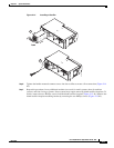
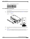
Step 3 The terminal block may be removed to make alarm cable connections (Figure 2-20).
124765