


82
Route Switch Processor (RSP8) Installation and Configuration Guide
OL-4920-02
Reference Information
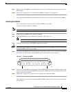
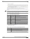
Software Configuration Register Settings
Settings for the 16-bit software configuration register are written into the NVRAM. Following are some
reasons for changing the software configuration register settings:
• To select a boot source and default boot filename
• To enable or disable the Break function
Note The Break function (software configuration register bit 8) when enabled allows you to send a Break
signal to the router during a system (re)boot. This stops the boot process and places the router into ROM
monitor mode. You can activate the Break function by using a dedicated Break key function on the
keyboard, or by entering the Ctrl-[ (left square bracket) key combination.
• To control broadcast addresses
• To set the console terminal baud rate
• To load operating software from Flash memory card or Flash Disk
• To enable booting from a Trivial File Transfer Protocol (TFTP) server
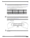
P1-6 J1-6 and J2-6 Data Set Ready (DSR)
P1-7 J1-7 and J2-7 Ground
P1-8 J1-8 and J2-8 Data Carrier Detect (DCD)
P1-13 J1-13 and J2-13 YCBL Detect Ground
P1-19 J1-19 and J2-19 YCBL Detect
P1-20 J1-20 and J2-20 Data Terminal Ready (DTR)
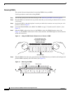
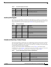
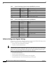
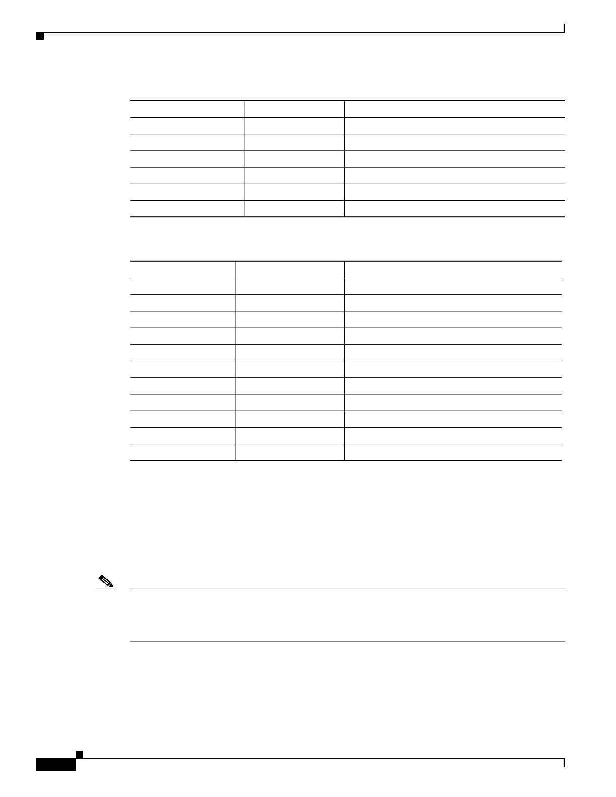
Table 8 Auxiliary Y-Cable Signals (Product Number CAB-RSP8AUX=)
Male DB-25 Pins Female DB-25 Pins Signal Description
P1-1 J1-1 and J2-1 Ground
P1-2 J1-2 and J2-2 TxD
P1-3 J1-3 and J2-3 RxD
P1-4 J1-4 and J2-4 RTS
P1-5 J1-5 and J2-5 CTS
P1-7 J1-7 and J2-7 Ground
P1-8 J1-8 and J2-8 DCD
P1-13 J1-13 and J2-13 YCBL Detect
P1-19 J1-19 and J2-19 YCBL Detect Ground
P1-20 J1-20 and J2-20 DTR
P1-22 J1-22 and J2-22 Ring
Table 7 Console Y-Cable Signals (Product Number CAB-RSP8CON=) (Continued)
Female DB-25 Pins Male DB-25 Pins Signal Description