


49
5
Topspin 360 LEDs
The following sections appear in this chapter:
• “Introduction” on page 49
• “Topspin 360 System LED” on page 50
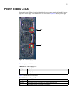
• “Power Supply LEDs” on page 51
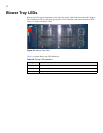
• “Blower Tray LEDs” on page 52
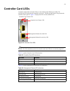
• “Controller Card LEDs” on page 53
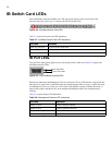
• “IB Switch Card LEDs” on page 54
• “IB Port LEDs” on page 54
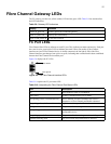
• “Fibre Channel Gateway LEDs” on page 55
• “FC Port LEDs” on page 55
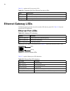
• “Ethernet Gateway LEDs” on page 56
• “Ethernet Port LEDs” on page 56
Introduction
LEDs on your Topspin 360 and installed components indicate hardware status. The sections in this
chapter explain the LED indications for the chassis and the components in the chassis.
LED indicators are appear on the following components:
• power supplies
•blowers
• controller cards
• InfiniBand cards
• Fibre Channel cards