


CHAPTER
5-1
Cisco SFS 7000P and SFS 7000D InfiniBand Server Switches Hardware Installation Guide
OL-10853-01
5
Managing the Switch
This chapter describes how to manage the Cisco SFS 7000P and SFS 7000D Server Switches hardware.
The following sections appear in this chapter:
• LEDs, page 5-1
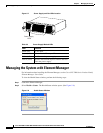
• Managing the System with Element Manager, page 5-4
• Displaying System Information, page 5-6
LEDs
The Cisco SFS 7000P and SFS 7000D Server Switches have the following types of LED indicators:
• Chassis Status LEDs, page 5-1
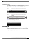
• InfiniBand Port LEDs, page 5-3
• Power Supply LEDs, page 5-3
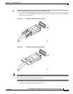
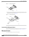
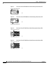
Chassis Status LEDs
The front of the chassis has a single bi-color chassis status LED. The rear of the chassis has one green
and one yellow chassis status LED that convey the identical information as the single chassis status LED
in the front of the chassis. See Table 5-1 for information about interpreting the chassis status LED and
see Figure 5-1 through Figure 5-4 for the locations of the chassis status LEDs.
Table 5-1 Interpreting the Chassis Status LED
Color Indication
Off No system power or LED failure.
Yellow (solid) Operator intervention required. A system error was detected,
such as a fan error, a POST failure, or a power supply failure.
The ! label (available on the back of the chassis) indicates a
failure.
Yellow
(blinking)
Initiated automatically during the LED test that follows the
application of power (16 seconds).
Solid green Indicates proper operation and no critical errors.