


Comments to ucs-docfeedback@cisco.com
11
Cisco UCS B230 Blade Server Installation and Service Note
OL-23811-01
Installing and Removing a Solid State Drive
Caution To prevent ESD damage, wear grounding wrist straps during these procedures and handle modules by
the carrier edges only.
Replacing an SSD with a drive of the same size, model, and manufacturer generally causes few problems
with UCS Manager. If the drive being replaced was part of a RAID array we recommend using a newly
ordered drive of identical size, model, and manufacturer to replace the failed drive. Cisco recommends
following industry standard practice of using drives of the same capacity when creating RAID volumes.
If drives of different capacities are used, the useable portion of the smallest drive will be used on all
drives that make up the RAID volume. Before upgrading or adding an SSD to a running system, check
the service profile in UCS Manager and make sure the new hardware configuration will be within the
parameters allowed by the service profile.
Disk and RAID troubleshooting information is in the Troubleshooting Server Hardware chapter of the
Cisco UCS Troubleshooting Guide. The B230 uses a built-in LSI SAS 2008 RAID controller (onboard
version of the LSI MegaRAID 9240) .
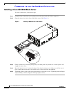
Installing an SSD Drive
To install an SSD drive sled in a B230 blade server, follow these steps:
Step 1 Remove the blank faceplate, if necessary.
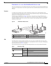
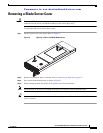
Step 2 With the drive label face up, align the drive with the desired drive bay and insert. (See Figure 1 to locate
the bays; Figure 3 shows a drive removal which is largely the reverse process.)
Step 3 Slide the drive into the opening in the blade server until the catch is secured. You should feel the catch
click into place.
Step 4 Give a gentle push to the rear to make sure the drive is fully seated.
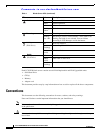
Step 5 Check the LEDs on the blade server to make sure the drive is functioning as expected. (See Table 1.)
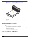
Removing an SSD Drive
To remove a drive from a blade server, follow these steps:
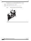
Step 1 Squeeze the catch mechanism to release the drive. (See Figure 3, callout 1.)
Step 2 Pull the drive from its slot. (See Figure 3, callout 2.)