


CBM-910 User’s Manual
CITIZEN
19
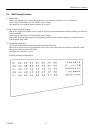
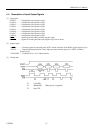
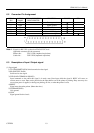
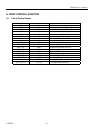
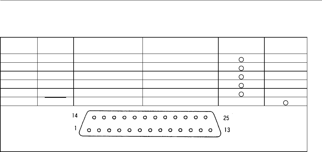
6.2 Connector Pin Assignment
SIGNAL SIGNAL SIGNAL DIRECTION FUNCTION RS-232C TTL
PIN NAME HOST-PRINTER
1 FG Frame ground
7 GND Signal ground
2 TD
←
Transmit data
3 RD
→
Receive data
20 DTR
←
Printer BUSY signal
23 RESET
→
Printer reset signal
Note: 1. Signals for RS-232C are based on EIA RS-232C level.
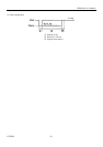
Applicable connector (D-sub connector)
Printer side : 17LE-13250 (Anphenol equivalent)
Cable side : 17JE-23250 (Anphenol equivalent)
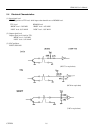
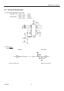
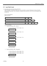
6.3 Description of Input / Output signal
(1) Input signal
1) TD (TRANSMIT DATA) Serial transmission data signal.
2) RD (RECEIVE DATA)
Serial receive data signal.
3) DTR (DATA TERMINAL READY)
Input command or data while this signal is in ready state. Data input while the signal is BUSY will cause an
overrun error to occur. Data can be provided to the input buffer even if the printer is printing. Busy state may also
occur when power is applied, or during test printing, on-line, or when the printer is reset.
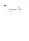
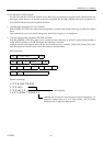
4) RESET
Signal resets the entire printer. (More than 4ms.)
5) FG(FRAME GND)
Case ground.
6) GND
Signal ground for the circuit.