


5. Installation
25
5-4. Installation
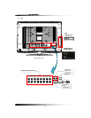
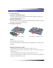
5-4.1. Camera Connection
▫ Connection of 6pin MINI DIN Cameras
Connect the supplied cameras to the Camera Input (6pin mini DIN jack) on the back of the
system as shown in [Fig. 5-2 Rear View].
▫ Connection of BNC Cameras
Connect the BNC cameras (not included) to the Camera Input (BNC connector) on the back
of the system as shown in [Fig. 5-2 Rear View].
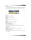
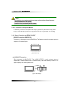
5-4.2. Installation of the Monitor
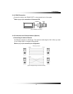
[Fig. 5-4-1 Removing mounting bracket] [Fig. 5-4-2 Cover the mounting bracket hole]
▫ Desktop
- Place the system on the flat surface.
- Do not place this product near a bathtub, kitchen sink, wet basement, over a radiator, or heat
generator.
▫ Installation of the system on the wall
- Place the system on the flat surface with soft fabric as shown in Fig. 5-4-1.
- Separate the mounting bracket by removing three screws on the rear of the system as
shown in Fig.5-4-1.
- Cover the mounting bracket hole with the provided lid as shown in Fig. 5-4-2.
- The wall mounting bracket is not included in the system and refer to the manufacturer’s
instructions on how to install it to the wall.