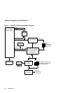
2–4 System Configuration and Connectors
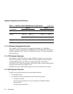
AlphaPC 164SX Configuration Switches
2.1 AlphaPC 164SX Configuration Switches
The AlphaPC 164SX motherboard has a switchpack located at SW1, as shown previ-
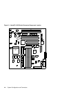
ously in Figure 2–1. The switches set the hardware configuration and boot options.
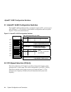
Figure 2–2 shows the switch functions.
Figure 2–2 AlphaPC 164SX Configuration Switches
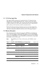
2.2 CPU Speed Selection (CF[6:4])
The clock synthesizer at U45 makes it possible to change the frequency of the
microprocessor’s clock output. The switch configuration is set in SW1, CF[6:4].
These three switches set the speed at power-up as listed in Figure 2–2. The
microprocessor frequency divided by the ratio determines the system clock
frequency.
CF Bit: 400 MHz 533 MHz
41 1
51 0
61 1
CF0
CF1
CF2
CF3
CF4
CF5
CF6
CF7
01
Password Bypass: 0 bypasses password protection
1 requires AlphaBIOS password
Fail-Safe Booter: 0: Fail Safe
1: AlphaBIOS or SRM console
Note:
All other combinations
are reserved.
Note: Switch defaults are in bold.
Mini-Debugger: 0 enables Mini-Debugger
1 disables Mini-Debugger
CF Bit: .5MB 1MB 2MB Reserved
00 1 01
10 0 11


